8
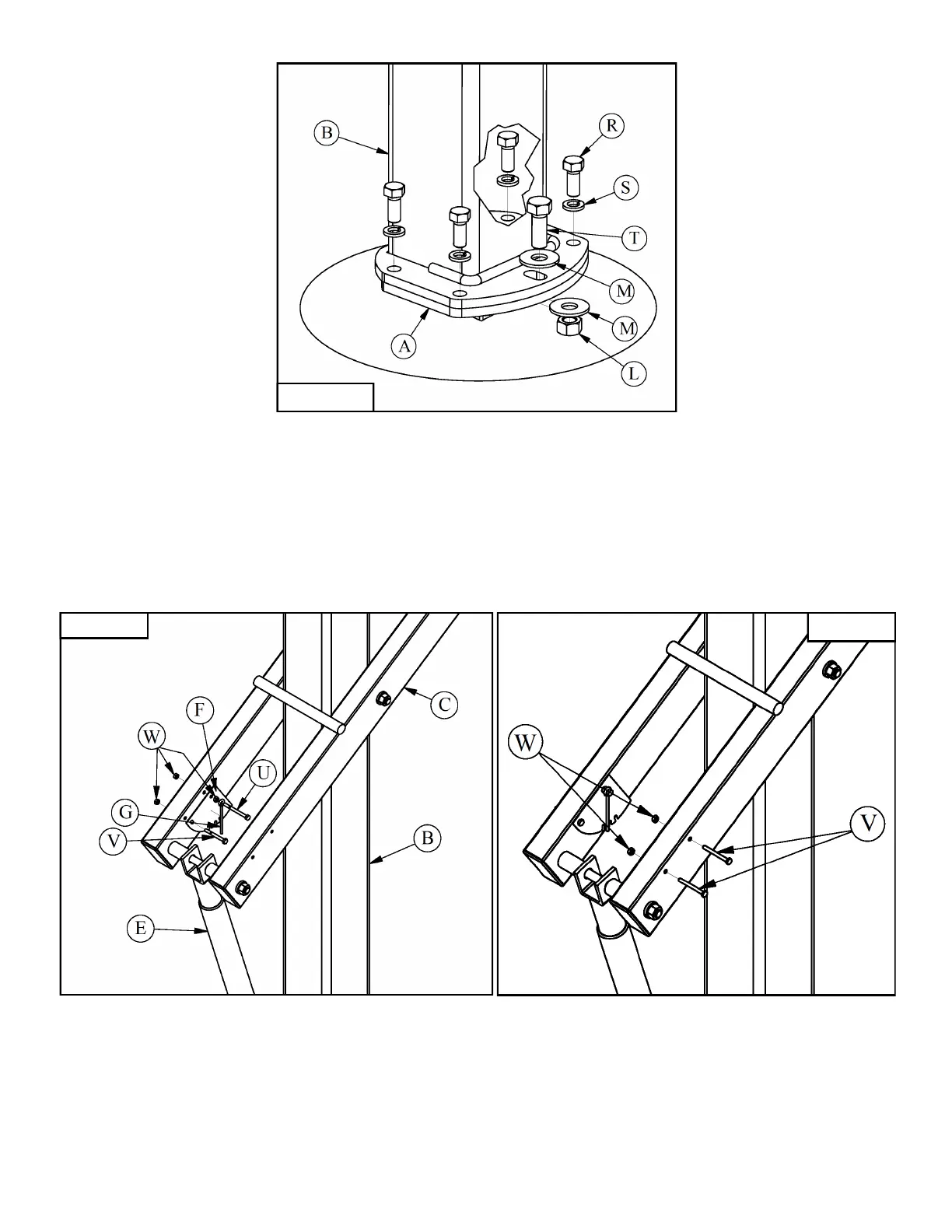
Figure 16
17. Attach Height Gauge (F) to the Lower Arm (C) with a 1/4” X 2 1/2” Hex Bolt (V) and 1/4”Hex Nut (W) in
the back mounting hole. Slide the Pointer (G) onto a 1/4”-20 X 3”Hex Bolt (U) then install one
1/4” Hex Nut (W) against the Pointer (G) with just enough slack to let the Pointer (G) rotate freely on the
1/4”-20 X 3” Hex Bolt (U). Pass this assembly through the front mounting hole in the Lower Arm (C) and
tighten with the remaining 1/4” Hex Nut (W). You must tighten the 1/4” Hex Nuts (W) against each other
to lock this assembly in place, if you tighten the 1/4”-20 X 3” Hex Bolt (U) you will also tighten the
assembly against the Pointer (G). The Pointer (G) must rotate freely on the 1/4”-20 X 3” Hex Bolt (U)
once installed to accurately indicate your systems height. Leave the Height Gauge (F) hardware loose.
See Figure 17.
18. Crank the system up so the Rim (CC) is at 10’, use a tape measure to assure the rim is at 10’. Adjust the
Height Gauge (F) by rotating it so that it reads 10’ then tighten the Height Gauge (F) hardware. Fill holes
on the other side of the Lower Arm (C) with the 1/4” X 2 1/2” Hex Bolts (V) and 1/4” Hex Nuts (W).
See Figure 18.
19. Install Pole Pad (DD) & Backboard Padding (EE) if applicable per the instructions included with them.
Figure 17 Figure 18
 Loading...