4
Figure 8
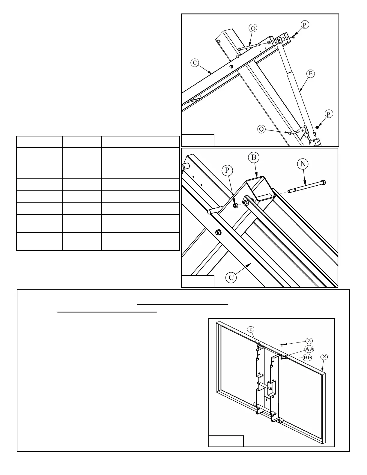
9. Attach the Crank (E) to the Pole (B) using a
5/8” X 5” Hex Bolt (Q) and 5/8” Lock Nut (P).
Attach the other end of the Crank (E) to the
Lower Arm (C) with a 5/8” X 12” Hex Bolt (O)
and 5/8” Lock Nut (P). The Crank (E) may
need to be extended to align the bolt holes.
Tighten hardware snug against Lower Arm (C)
and the tabs on the Pole (B), then back off 1/2
turn. See Figure 8.
10. Attach Upper Arms (D) to the Pole (B) using a
5/8” X 11” Hex Bolt (N) and 5/8” Lock Nut (P).
Tighten hardware then back off 1/2 turn. This is
a pivot point, do not over tighten. See Figure 9.
11. Look at the table above to determine which
instructions to follow for assembly of the
Backboard (X).
Figure 9
Backboard Required H-Frame Package
BA42GHT
HT6HFRAME2 HT6072G &
PR98GHT
BA42UHT
HT6HFRAME2 PR98UHT
BA487
HT5HFRAME2 HT6060G
BA487SM
HT5HFRAME2 HT6060GSM
BA487U HT5HFRAME2 PR98UHTJR
BA47U
PR98SHTBKT2
(hardware packed with frame)
PR98SHT
BA472
PR98SHTBKT2
(hardware packed with frame)
PR98SXLHT
HT6060G, HT6060GS, PR98UHTJR, PR98GHTJR
1. Use the 5/16" X 1" Machine Screws (Z), 5/16" Lock
Washers (AA) and 5/16" Hex Nuts (BB) to install
Backboard H-Frame (Y) into Backboard (X).
See Figure 10.
2. Once Backboard (X) is assembled refer to
instruction 12 to complete system assembly.
Figure 10