5
HT6072G, PR98GHT, PR98UHT
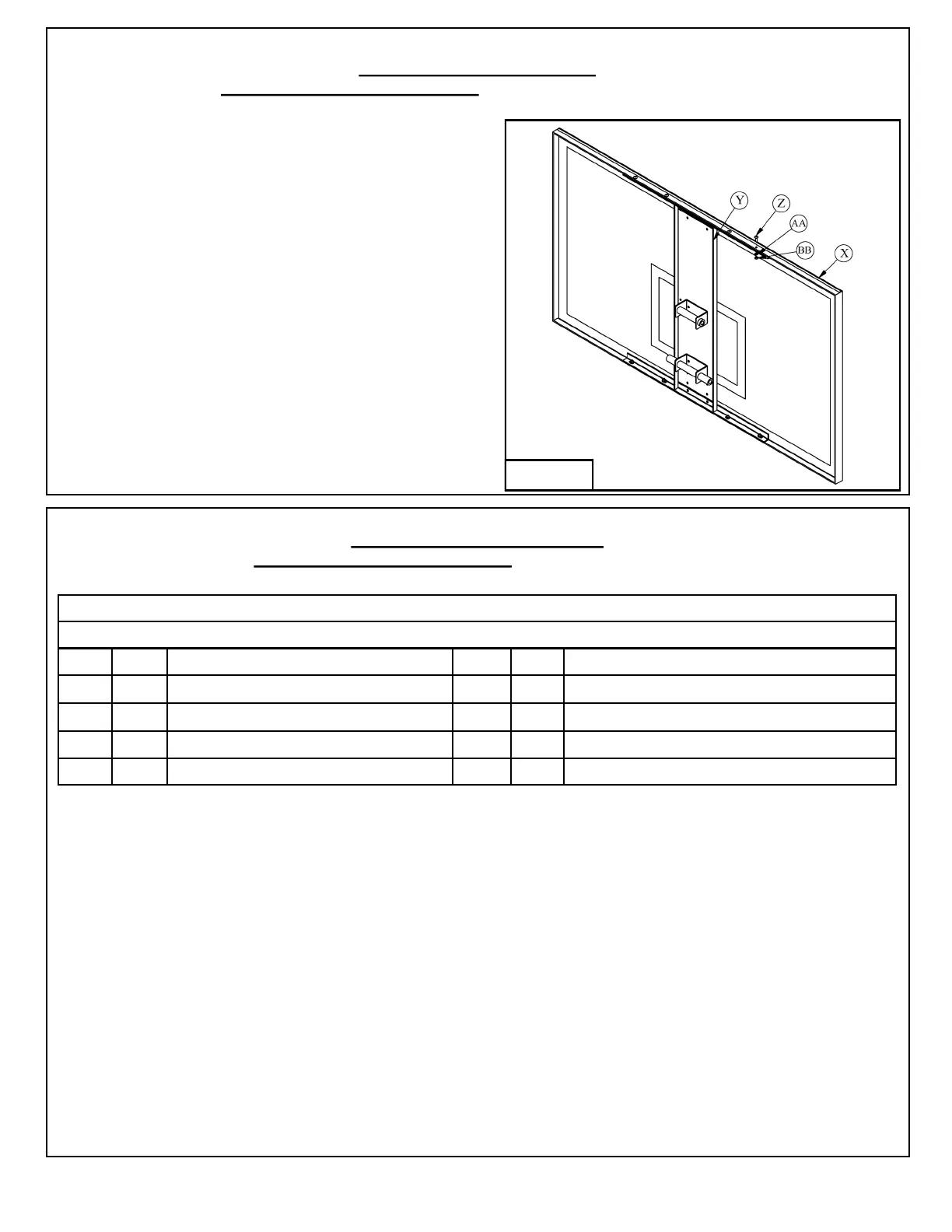
Figure 11
2. Once Backboard (X) is assembled refer to
instruction 12 to complete system assembly.
1. Use the 5/16" X 1" Machine Screws (Z), 5/16"
Lock Washers (AA) and 5/16" Hex Nuts (BB)
to install Backboard H-Frame (Y) to Backboard (X).
See Figure 11.
PR98SHT, PR98SXLHT
1. Use 5/8” X 12” Hex Bolt (O), 5/8” X 11” Hex Bolt (N), and 5/8” Lock Nuts (P) to attach Backboard
H-Frame (Y) to Lower Arm (C) and Upper Arms (D). Do not overtighten hardware, make sure the
Lower Arm (C) and Upper Arms (D) pivot and adjust up and down freely. See Figure 12.
2. Hang Backboard (X) over the top lip of Backboard H-Frame (Y). Use 7/16" X 1 1/2" Carriage Bolts (1),
7/16" Flat Washers (2), 7/16" Lock Washers (3) and 7/16" Hex Nuts (4) in the top two holes of
Backboard (X) and Backboard H-Frame (Y). Hand tighten hardware at this time. See Figure 12.
3. Use 3/8" X 1 1/2" Hex Bolts (5), 3/8" Flat Washers (6), 3/8" Lock Washers (7) and 3/8" Hex Nuts (8) to
install Rim (CC). Hand tighten hardware at this time. See Figure 12.
4. Level Backboard (X) and Rim (CC). Tighten all hardware.
5. Refer to instruction 14 to complete system assembly.
P A R T S L I S T
**Packaged with H-Frame
Item Qty Description Item Qty Description
1 2 7/16" X 1 1/2" Carriage Bolt** 5 4 3/8" X 1 1/2" Hex Bolt**
2 2 7/16" Flat Washer ** 6 8 3/8" Flat Washer (packaged with rim hardware)
3 2 7/16" Lock Washer** 7 4 3/8" Lock Washer (packaged with rim hardware)
4 2 7/16" Hex Nut** 8 4 3/8" Hex Nut (packaged with rim hardware)
 Loading...