Do you have a question about the Bissell PROHEAT PRO-TECH #1699 and is the answer not in the manual?
Procedure for performing high voltage tests on repaired units for customer safety.
Test to ensure grounding continuity between electrical components.
Basic checks of the trigger mechanism's travel and the SmartMix knob's resistance.
Inspection of tank seals, valves, gaskets, and nozzle window tab alignment.
Instruction to remove the belt access door for inspection or maintenance.
Checking motor shaft for smooth rotation and preparing the unit for functional tests.
Listening for abnormal motor noises and verifying the flow indicator's spin.
Testing the unit's ability to suction water and spray solution.
Adjusting the SmartMix piston and checking tanks for proper function.
Performing spray tests, checking for air bubbles, and locating leaks.
Ensuring hoses are not pinched and clearing any blockages in lines.
Testing heater functionality and confirming necessity before replacement.
Checking the proper alignment of the nozzle window and its components.
Steps for removing the main housing and the motor duct.
Disconnecting the flow indicator, spray tips, and pump outlet tube.
Removing the motor cover, duct, and disconnecting all motor wires.
Saving old motor gaskets and cleaning the motor cover area.
Installing new gaskets and connecting the ground wire to the motor.
Connecting hot, neutral, and ground terminals to the new motor.
Properly routing motor wires and inserting the gasket into the housing.
Reassembling the motor cover, duct, and securing them with screws.
Reinstalling spray tips, flow indicator, tubing, and upholstery duct.
Reassembling the upholstery duct, belt, and main housing.
Testing brush rotation, motor operation, and overall unit functionality.
Ensuring correct positioning of the foot pedal and loading the SmartMix.
Properly seating the nozzle gasket and aligning the unit cover.
Aligning the diverter valve and upholstery duct before closing.
Cleaning the flow indicator and replacing the nozzle window.
Reinstalling access doors, tanks, and performing a final unit test.
Steps to unplug the unit and remove tanks, spray tips, belt, and lines.
Procedure for removing the pump unit after detaching retaining screws.
Installing the stretch belt onto the new pump and seating it correctly.
Reconnecting tubing, brush, cogbelt, retainer arm, and spray tips.
Testing the pump operation by plugging in the unit and using the trigger.
Removing screws, bolts, and nuts from the lower handle assembly.
Disconnecting all wire connections from the unit's light.
Disassembling the handle and disconnecting circuit board wires.
Removing the Perfect Pass housing which contains the circuit board.
Removing the main housing and the right side wheel.
Gently removing the old speed sensor and snapping in the new one.
Properly routing the speed sensor wire to the circuit board.
| Brand | Bissell |
|---|---|
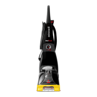
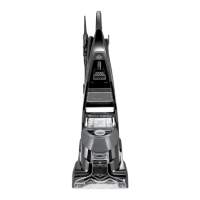
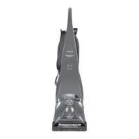
| Model | PROHEAT PRO-TECH #1699 |
| Category | Vacuum Cleaner |
| Language | English |