Embedded version
The embedded version calls for a SI3000/xx galvanised steel box ( “a” in fig.1 ) that must be embedded into the wall.
Embedding boxes are different for each of the 8 possible configurations, from the SI3000/12 AV0003/12 ( 1 row x 2 modules
) to the SI3000/43 AV0003/43 ( 4 rows x 3 modules ).
The BM3000/X wall support will be fixed inside the embedding box by way of the screws provided.
Assembly has to be completed as previously described for surface mounting. The main difference is the use of specific
frames for the embedding version ( KCI 3000/xx ). As for surface-mounting, also the embedding version frames are different
for each of the 8 possible configurations (from the KCI3000/12 AV0037/12 –
1 row x 2 modules – to the KCI3000/43 AV0037/43 - 4 rows x 3 modules ).
ATTENTION:
Do not attempt to embed the wall support directly, without using the intended embedding box.
Such an operation, although theoretically possible, would require extreme accuracy for an acceptable result.
If correctly assembled, the panel meets the IP33 rating for solids and water penetration. For further information on the other
modules, see the specific manuals.
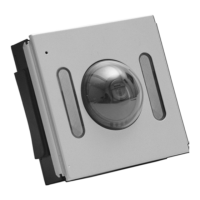
GVM3000 (AV0060) and GVCM3000 (AV0078) VIDEO MODULES
A video module is to be coupled with a GCM3000/2 ( AV00502/2 ) audio module to complete a Bitron Video DOMULAR 3000
video doorphone system.
Video modules are available in two different versions:
• GVM 3000 ( AV 0060 ) with B/W camera
• GVCM 3000 ( AV 0078 ) with colour camera
The two models differ for the type of camera and for the kind of illumination used: invisible infrared LED’s on B/W modules,
high-efficiency white LED’s in colour systems. Descriptive labels on the back of the modules identify each version clearly.
Our long experience in video systems technology results in a very reliable image transmission, free from environmental
interference. Thanks to our differential video transmission technology, high-quality pictures are transmitted long distances
without need for expensive and bulky coaxial cables. Only 5 wires are used to connect the visitor panel to the individual
monitor stations, and the video signal is transmitted over telephone-type twisted-pairs.
Main features:
1) “Balanced” video output for transmission without coaxial cable
2) Built-in illuminator: infrared for GVM3000 ( AV0060 ) and white light for GVCM3000 ( AV0078 )
3) Manual pan-tilt camera adjustments
4) Defogging heater
5) Timer function for monitor lighting ( adjustable )
6) Monitor switch-off upon lock activation ( excludible )
7) Disabling of self-start ( surveillance ) feature when any other monitor in the system is on.
TECHNICAL FEATURES
• Power supply …………………………………..……………………………………..….……………... 12-15VAC
• Current rating of electric lock relay contact………………………………….......…………………... 120mA
• Tension level on CD wire for lock control.…………………..……………………………….………. 3VDC
• Max current of the electric lock relay contact ……………...…………………………….………….. 5Aac
• Independent volume adjustments for internal and external audio (loudspeaker/microphone)
• Excludible call confirmation tone
• Opening timer adjustable in 2 positions ………………………………………….………………….. 3-30 sec
• Selection of electronic call tone……………single, two-tone or 100Hz buzzer
• Electric lock protection in case of door opener control jamming
• Possibility of microphone relocation in case of Larsen effect in noisy environments
TERMINALS BLOCK
GVM3000 ( AV0060 ) and GVCM3000 ( AV0078 ) video modules have the following connection terminals ( see fig. 5 ):
E Video group self-start input
This terminal is to be connected to “E” wire from MV80, MV100 and MV3000 new-generation monitors.
A specific button on the monitors allows to switch-on the video group for surveillance purposes, without need for
a prior visitor call. This function is enabled only when no other calls are in progress. Otherwise, it is needed to
wait to the end of timer time, or until the electric lock is released ( if the switch-off at lock activation has been
programmed ), before self-start function becomes available again.
V Standard ( compound ) video output.
A compound video signal output is available at this terminal for systems fitted with a coaxial cable ( 75Ohm
impedance ). The coax is to be connected between the module “V” (core) and “1” (shield) terminals.
This option can be used for sending a standard video signal to a CCTV monitor, or instead twisted-pair cable in
case of systems retrofit.
B Positive differential video output
This terminal connects the “B” wire of all monitors.
A Negative differential video output
This terminal connects the “A” wire of all monitor.
1 System common wire
This terminal corresponds to the riser wire connecting terminal “1” of monitors and doorphones.
3 Monitors power supply terminal
This terminal corresponds to the riser wire connecting terminal “3” of monitors. Power supply in not always
present in the riser, as it depends on the jumpers setting.
- Power supply negative
It is to be connected to the – wire coming from the A70 ( AN7361 ) power supply.
+ Terminal for positive power supply
It is to be connected to the + wire coming from the A70 ( AN7361 ) power supply.
CONFIGURATION JUMPERS
GVM3000 ( AV0060 ) and GVCM3000 ( AV0078 ) devices have 2 programming jumpers allowing to:
• Activate or deactivate the self-start (surveillance) function upon electric lock release ( jumper “AP T” in fig. 6 )
• Select the output tension pattern on terminal “3” ( jumper “C N” in fig. 6 )
Auto switch-off upon lock release command ( AP T jumper )
This jumper activates the monitor and group switch-off every time the door is opened.
• With jumper in “AP” position (default setting) the monitor is switched off when the door opener is pressed
• With jumper in “T” position monitor is switched off at the end of the timer lapse.
NOTE:
If a new call arrives before the timer lapse has run out, the monitor will switch off independently of the jumper
setting.
Door opener timer’s setting ( TP jumper )
This jumper allows the door opening control time adjustment.
Independently from how long a door opener button is pressed 1( on doorphone or monitor ), the panel will activate the
electric lock for a pre-set time. At the end, the activation signal will be stopped until the opener button is released and
pressed another time.
This function avoids the electric lock being damaged in case of accidental door opener jamming.
The timer has two possible settings:
• Jumper inserted (default setting): the lock activation time lasts 3 seconds approx.
• Jumper removed: the lock activation time is extended to about 30 seconds.
Definition of output “3” operation pattern ( “N-C” jumper )
This jumper defines the way of functioning of the riser power supply output ( terminal 3 ).
Possible tones are:
Pag.13
Pag. 12
 Loading...