5.3. Legend for the schematic
diagrams
5.4. Connections
Legend
B1 Control unit
B2 Control unit of capacity regulation (option)
F1 Main fuse
F2 Compressor fuse
F3 Control circuit fuse
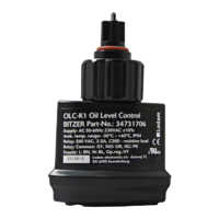
F4 Oil level switch
F5 High pressure cut-out
F6 Low pressure cut-out
F12 Fuse of crank case heater
F13/F14 Thermal overload motor PW1 / PW2
H1 Signal light “Compressor over temperature fault”
H2 Signal light “Oil supply fault”
K1/K2 Motor contactors PW1 / PW2
K1T/K2T Time relays “part winding” / pause time
M1 Compressor
Q1 Main switch
R1..3/R1..R6 PTC sensors in motor windings
R7 PTC sensor in cylinder head/discharge gas tempera-
ture sensor (option)
R8 Crank case heater (option)
S1/S2/S3 Control switch
Y1 Solenoid valve “start unloading” (option)
Y2 Solenoid valve “liquid line”
Y3 Solenoid valve “capacity regulation” (option)
View colour Function
Brown L; Phase
Blue N; Neutral
Grey C; Common signal
Orange NO; Normal open
Pink NC; Normal closed
Violet (only OLC-K1) D1; Compressor running
Technical manual OLC-D1, OLC-K1
Page 9
 Loading...