5KW-541-2
Die weiteren Schritte sind für Typ 1
und Typ 2 identisch
• Befestigungsschrauben des Ab-
schlussdeckels (5) herausdrehen
• Zwei dieser Schrauben in die Ab-
drückgewinde eindrehen und durch
gleichmäßiges Anziehen den Ab-
schlussdeckel (5) vom Gehäuse
abdrücken
• Abschlussdeckel (5) mit der Hand
von der Welle abziehen
Achtung!
Die Wellenoberfläche ist
empfindlich gegen Verkratzen
und Riefenbildung.
Ablagerungen auf der Welle mit
Putztüchern oder ölgetränkten
Polierleinen bzw. Schleifleinen
mit Körnung 280 (oder feiner)
entfernen!
• Die Gewindestifte im Gleitring (1)
lösen und entnehmen (nicht wieder
verwenden!)
• Anschließend den Gleitring von
Hand von der Welle abziehen
Achtung!
Falls Gewindestifte im Gleitring
verbleiben, besteht beim Ab -
ziehen Gefahr von Riefenbildung
auf der Welle!
• Dichtscheibe (8) von der Welle
nehmen
• Radialdichtring (9 bzw. 10) aus der
Nut der Welle, die O-Ringe (4 und
7) aus der Aussparung der Dicht-
scheibe und aus der Nut des
Abschlussdeckels entnehmen
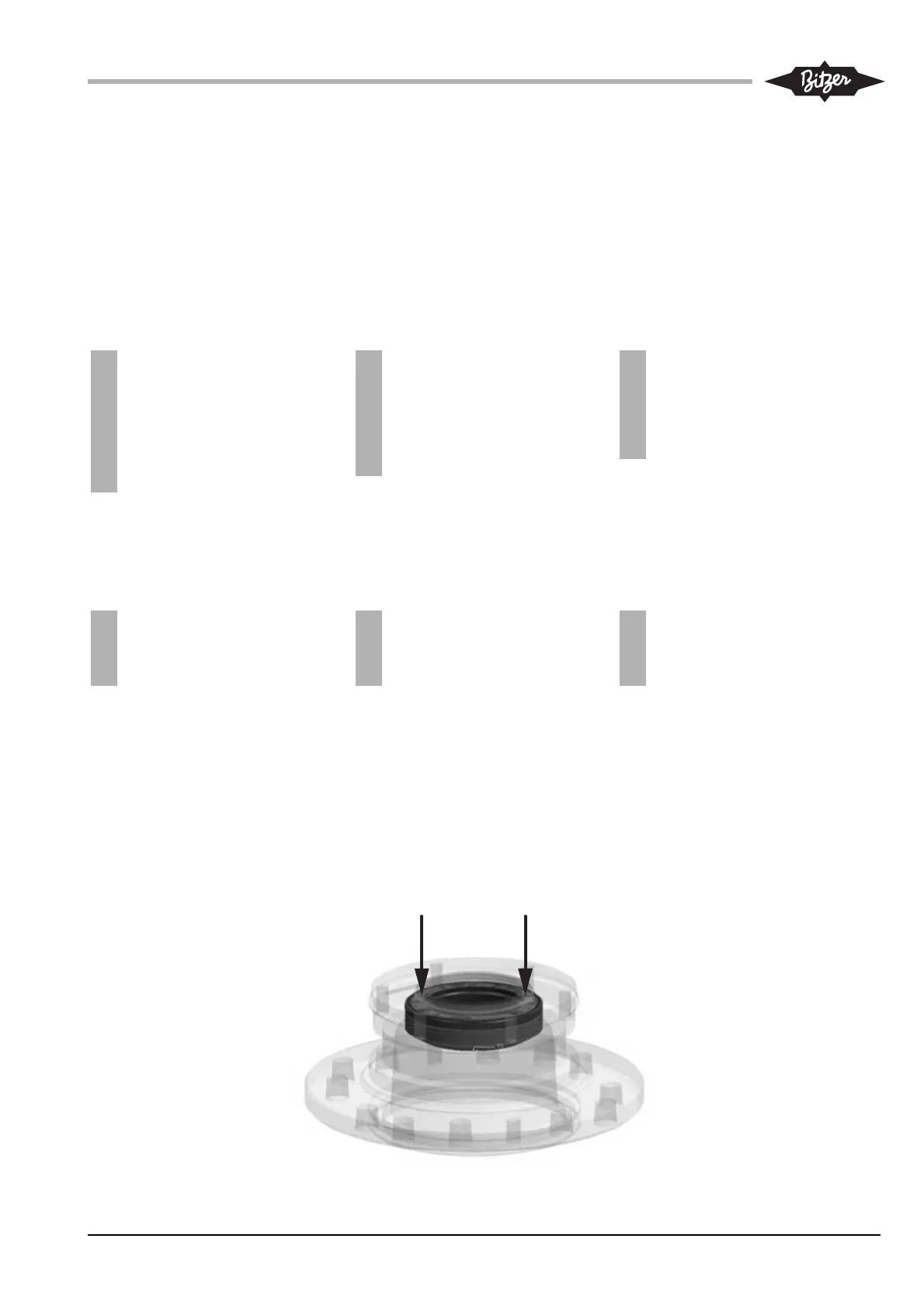
• Gegenring (2) der Wellenabdich-
tung von Hand aus dem Abschluss-
deckel (5) herausdrücken (Abb. 1)
The following steps are identical
for type 1 and type 2
• Screw out the fastening screws of
the sealing cover (5)
• Screw in two of these screws into
the forcing thread and, by pulling
evenly, push the sealing cover (5)
away from the housing
• Pull off the sealing cover (5) from
the shaft manually
Attention!
The shaft seal is susceptible to
scratches and striation.
Remove coatings on the shaft
seal by using cleaning rags and
oil-soaked polishing cloths or
emery cloths with 280 (or finer)
grit!
• Loose and remove the set screws
inside the sliding ring (1) (do not
reuse!)
• Afterwards pull the sliding ring from
the shaft manually
Attention!
In case the set screws remain
inside the sliding ring, there is
imminent danger of striation on
the shaft during removal!
• Remove the sealing plate (8) from
the shaft
• Remove the radial gasket ring (9
res. 10) from the groove on the
shaft, the O-rings (4 and 7) from
the recess of the sealing plate and
from the sealing cover (5)
• Push the stationary ring (2) of the
shaft seal from the sealing cover
(5) manually (Fig. 1)
Les instructions suivantes sont iden-
tique pour type 1 et type 2
• Dévisser les vis de fixation du couver-
cle de fermeture (5)
• Introduire deux de ces vis dans les file-
tages de dégagement et serrer unifor-
mément pour décoller le couvercle de
fermeture (5)
• Enlever avec la main le couvercle de
fermeture (5) de l'arbre
Attention !
La garniture d'étanchéité est sen-
sible pour égratigner et striation.
Retirer des dépôts en utiliser des
chiffrons et de la toile à polir ou de
la toile émeri imbibée d'huile, grain
280 (ou plus fin) !
• Desserrer et enlever les vis sans tête
de la bague de glissement (1) (ne pas
les réutiliser !)
• Ensuite enlever avec la main la bague
de glissement de l'arbre
Attention !
Si les vis sans tête restent dans la
bague de glissement, il y a risque
de striation sur l'arbre lors du
retrait !
• Enlever la rondelle d'étanchéité (8) de
l'arbre
• Enlever le joint annulaire radial (9 res.10)
de la rainure de l'arbre, les joints annu-
laires (4 et 7) de l’évidement de la ron-
delle d'étanchéité et de la rainure du
couvercle de fermeture (5)
• Faire sortir la bague fixe (2) de la gar-
niture d'étanchéité avec la main du
couvercle de fermeture (5) (Fig. 1)
Abb. 1 Abschlussdeckel mit Gegenring
Fig. 1 Sealing cover with stationary ring
Fig. 1 Couvercle de fermeture avec bague
fixe
 Loading...