9
• Riemenscheibe über die
Stiftschrauben der Kupplung schie-
ben und mit Muttern (7) festschrau-
ben (Anzugsmoment 25 Nm).
Achtung!
Riemenscheibe muss sich von
Hand drehen lassen, ohne am
Magnet zu schleifen!
• Kabel (3) anschließen (polungsun-
abhängig), dabei von heißen Teilen
fernhalten (t
max
= 105°C).
Anleitungen für den Einbau anderer
Kupplungen auf Anfrage.
3.4 Absperrventile
Die Absperrventile können gedreht und
an unterschiedlichen Stellen montiert
sein (Anschlüsse siehe Seiten 12, 13).
!
!
• Slide pulley over the pin screws of
the clutch and screw down with
nuts (7) (tightening torque 25 Nm).
Attention!
You must be able to turn the pul-
ley by hand without it rubbing
against the magnet!
• Connect cable (3) (polarity is irrele-
vant here), and keep away from hot
parts (t
max
= 105°C).
Instructions for the installation of other
clutches upon request.
3.4 Shut-off valves
The shut-off valves can be rotated
and mounted in various positions (for
connections, see pages 12, 13).
!
!
• Glisser la poulie au-dessus des gou-
jons de l'embrayage et fixer avec les
écrous (7) (couple de serrage 25 Nm).
Attention !
La poulie doit pouvoir être tournée à
la main, sans frotter contre l'aimant !
• Raccorder le câble (3) (polarité ne joue
aucun rôle), et le tenir à l'écart des
parties chaudes (t
max
= 105°C).
Instructions pour le montage des autres
embrayages sur demande.
3.4 Vannes d’arrêt
Les vannes d’arrêt peuvent être tournées et
montées à différents endroits (pour les rac-
cords, voir pages 12, 13).
!
!
KB-540-3
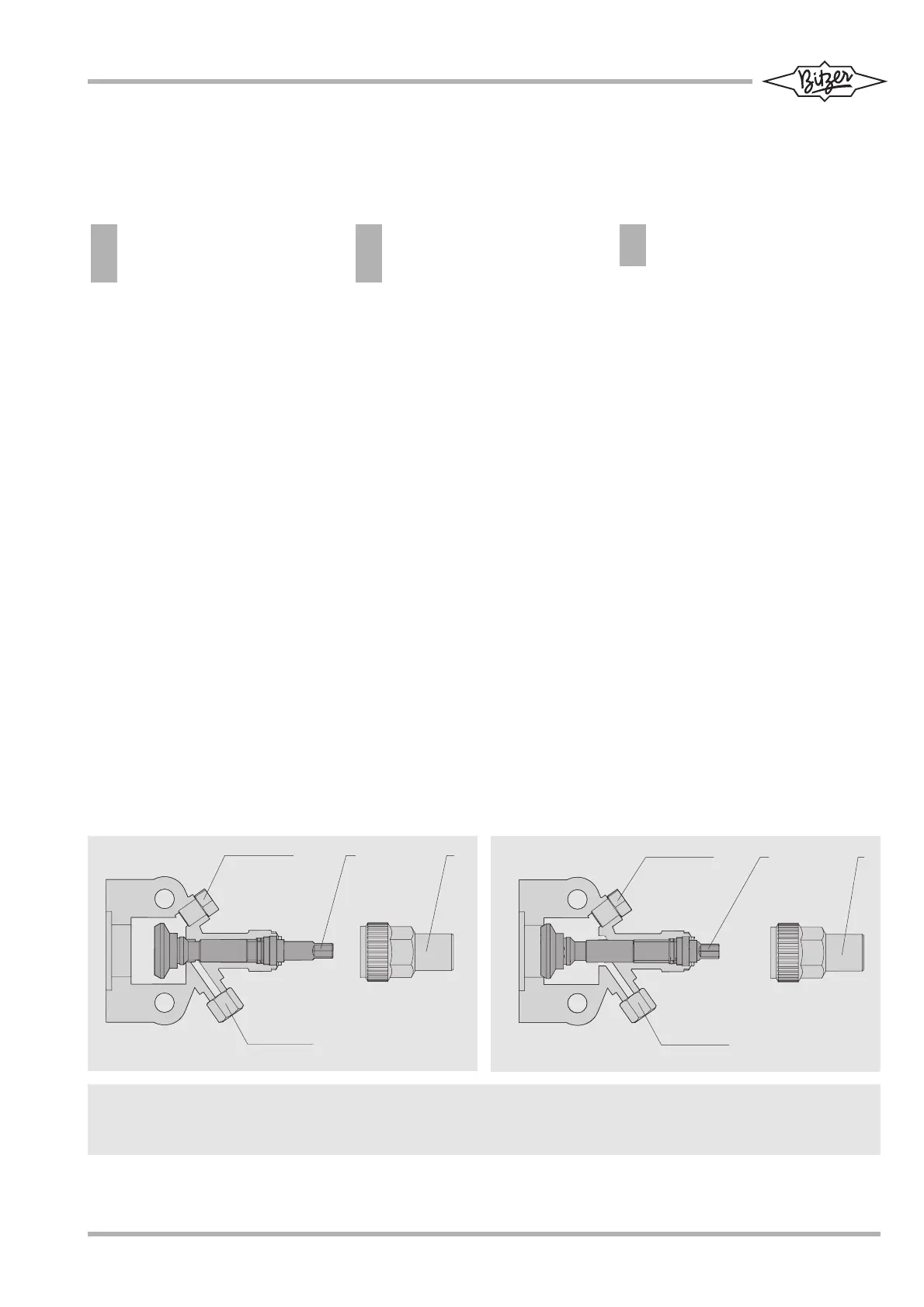
Abb. 5 Offenes Absperrventil (Betriebsstellung)
Fig. 5 Open shut-off valve (operating position)
Fig. 5 Vanne d’arrêt ouverte (position de fonctionnement)
Abb. 6 Geschlossens Absperrventil
Fig. 6 Closed shut-off valve
Fig. 6 Vanne d’arrêt fermée
3
7 / 1 6 ' ' - 2 0 U N F
4
1 / 8 ' ' - 2 7 N P T F
2 1
1
2
3
7 / 1 6 ' ' - 2 0 U N F
4
1 / 8 ' ' - 2 7 N P T F
1 Verschlusskappe
2 Spindel
3 Service-Anschluss (absperrbar)
4 Mess-Anschluss
1 Sealing cap
2 Spindle
3 Service connection (can be shut off)
4 Measurement connection
1 Capuchon
2 Tige
3 Raccord de service (obturable)
4 Raccord de mesure