14 KT-130-2
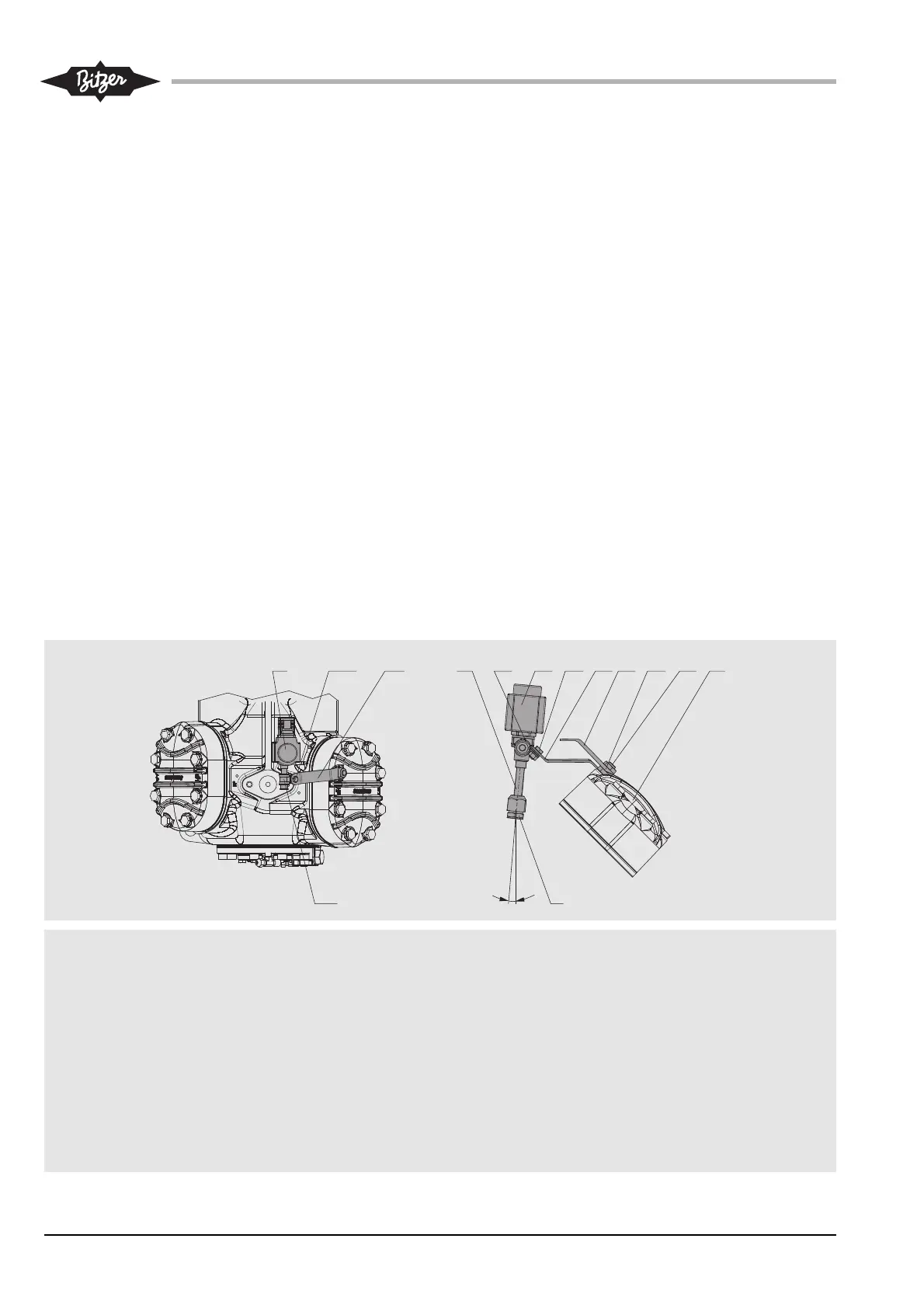
Abb. 6a Einbaupositionen des Einspritz-
ventils: 4Z-5.2(Y) .. 4N-12-2(Y)
Fig. 6a Mounting position of the injection
valve: 4Z-5.2(Y) .. 4N-12-2(Y)
Fig. 6a Position de montage de la vanne
d'injection: 4Z-5.2(Y) .. 4N-12.2(Y)
Typen 4Z-5.2(Y) .. 4N-12.2(Y)
(Abb. 6a)
• Das Befestigungsblech (5a) des
Einspritzventils mit einer Mutter
(M10), zusammen mit der Halter-
ung für den Zusatzventilator (E) an
den Zylinderkopf montieren
• Anstelle der normalen Zylinderkopf-
Sechskantschraube den zum
Lieferumfang des Zusatzventilators
gehörenden Gewindebolzen (C)
verwenden und bis auf den Gewin-
degrund eindrehen (Anzugs-
moment: 80 Nm)
Anordnung der sonstigen Bauteile,
siehe Abb. 6a.
• Zur Sicherung des Einspritzventils
dient die Rohrschelle (5b), die mit
dem Befestigungsblech (5a) ver-
schraubt wird (Schraube und
Mutter 5c/5d)
Types 4Z-5.2(Y) .. 4N-12.2(Y)
(fig. 6a)
• Mount the fixing plate (5a) of the
injection valve with a nut (M10),
along with the fixture of the additio-
nal fan (E) onto the cylinder head
• Instead of the normal cyclinder
head hexagon screw, use the
threaded bolt (C) belonging to the
additional fan kit and screw it down
to the thread base (tightening tor-
que: 80 Nm)
Arrangement of the remaining compo-
netents see fig. 6a.
• The injection valve is fixed by the
pipe clamp (5b) which is screwed
to the fixing plate (screw and nut
5c/5d)
Types 4Z-5.2(Y) .. 4N-12.2(Y)
(fig. 6a)
• Monter la tôle de fixation (5a) de la
vanne d'injection avec un écrou (M10),
simultanément avec le fixage (E) du
ventilateur additionnel
• À la place de la vis à tête hexagonale
normal de la tête de culasse, introdui-
re, jusqu'aufond du filet, un goujon
filetés (C) qui fait partie de la kit de
montage du ventilateur additionnel
(couple de serrage: 80 Nm)
Pour l'arrangement des autres compo-
sants voir fig. 6a.
• Le maintien de la vanne d'injection est
assuré par le collier d'attache (5b) qui
est vissé à la tôle de fixation (5a) (vis
et écrou 5c/5d)
Darstellung des Einspritzventils (5) mit
Magnetspule (B)
4 Einspritzdüse
5 Einspritzventil
5a Befestigungsblech
5b Rohrschelle
5c Schraube M6x12
5d Mutter M6
A Zylinderkopf
B Magnetspule
C Gewindebolzen
D Muttern M10
E Halterung für Zusatzventilator
Injection valve (5) shown with solenoid
coil (B)
4 Injection nozzle
5 Injection valve
5a Fixing plate
5b Pipe clamp
5c Screw M6x12
5d Nut M6
A Cylinder head
B Solenoid coil
C Threaded bolt
D Nuts M10
E Fixture for additional fan
Représentation de la vanne d'injection (5)
avec la bobine magnétique (B)
4 Gicleur d'injection
5 Vanne d'injection
5a Tôle de fixation
5b Collier d'attache
5c Vis M6x12
5d Ecrou M6
A Tête de culasse
B Bobine magnétique
C Goujon fileté
D Ecrou M10
E Fixage de ventilateur additionnel