15KT-130-2
Typen 4VE(S)-7(Y) .. 6FE-44(Y)
(Abb. 6b und Abb. 6c)
Bei diesen Verdichtern erfolgt die
Befestigung des Einspritzventils am
Zylinderkopf mit einer Zylinderkopf-
schraube (A). Das Befestigungsblech
(5a) für den Zusatzventilator wird an
anderen Zylinderkopfschrauben mon-
tiert.
• Dazu die in Abb. 6b gekennzeich-
nete Schraube (A) am Zylinderkopf
lösen. Bei den Verdichtern 4VE(S)-
4NE(S) Distanzhülse (6) einfügen
und die beiliegende, verlängerte
Sechskantschraube M10 verwen-
den. Anschließend zusammen mit
dem jeweiligen Befestigungsblech
(5a) wieder am Zylinderkopf befe-
stigen (Anzugsmoment: 80 Nm)
• Danach das Einspritzventil über die
Rohrschelle (5b) mit dem Befesti-
gungsblech (5a) verschrauben
(Schraube und Mutter 5c/5d)
Anordnung der sonstigen Bauteile
siehe Abb. 6b und 6c.
Types 4VE(S)-7(Y) .. 6FE-44(Y)
(fig. 6b and fig. 6c)
For these compressors, fix the injec-
tion valve with the normal cylinder
head screw (A).
The fixing plate of the additional fan is
mounted at different cyclinder head
screws.
• Remove the cyclinder head screw
shown in fig. 6b. For the compres-
sors 4VE(S)-4NE(S) add a spacer
sleeve (6) and use the attached
longer hexagon head screw M10.
After that re-mount on the cyclinder
head along with the corresponding
fixing plate
(tightening torque: 80 Nm)
• After that, screw injection valve via
pipe clamp (5b) to the fixing plate
(5a) (screw and nut 5c/5d)
Arrangement of the remaining compo-
netents see fig. 6b and 6c.
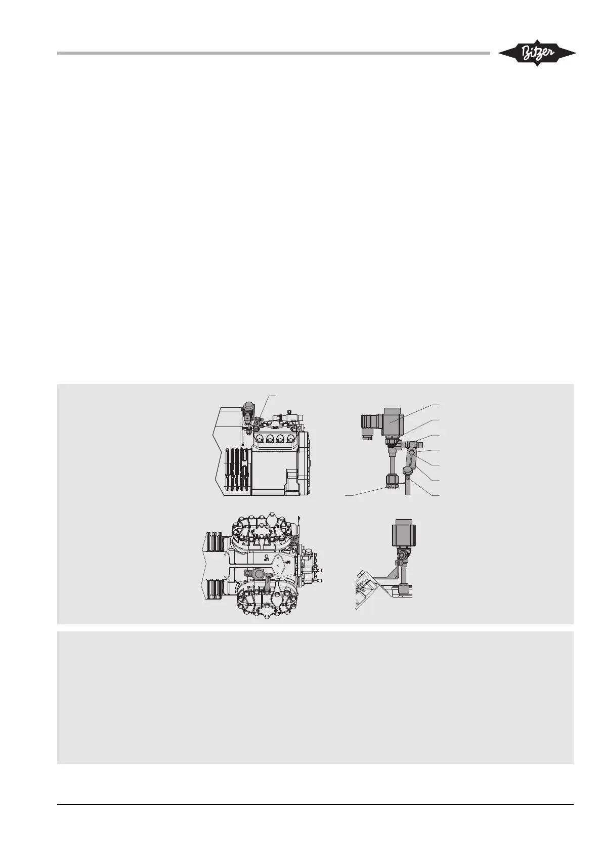
Abb. 6b Einbaupositionen des Einspritz-
ventils: 4VE(S)-7(Y) .. 4FE-28(Y)
Fig. 6b Mounting position of the injection
valve: 4VE(S)-7(Y) .. 4FE-28(Y)
Fig. 6b Position de montage de la vanne
d'injection: 4VE(S)-7(Y) .. 4FE-28(Y)
Darstellung des Einspritzventils (5) mit
Magnetspule (B)
4 Einspritzdüse
5 Einspritzventil
5a Befestigungsblech
5b Rohrschelle
5c Schraube M6x12
5d Mutter M6
6 Distanzhülse (4VE(S) .. 4NE(S))
A Zylinderkopfschraube
B Magnetspule
Injection valve (5) shown with solenoid
coil (B)
4 Injection nozzle
5 Injection valve
5a Fixing plate
5b Pipe clamp
5c Screw M6x12
5d Nut M6
6 Spacer sleeve (4VE(S) .. 4NE(S))
A Cylinder head screw
B Solenoid coil
Représentation de la vanne d'injection (5)
avec la bobine magnétique (B)
4 Gicleur d'injection
5 Vanne d'injection
5a Tôle de fixation
5b Collier d'attache
5c Vis M6x12
5d Ecrou M6
6 Douille d'espacement (4VE(S) .. 4NE(S))
A Vis de tête de culasse
B Bobine magnétique
4VE(S)-7(Y) .. 4NE(S)-14(Y)
4JE-15(Y) .. 4FE-28(Y)
Types 4VE(S)-7(Y) .. 6FE-44(Y)
(fig. 6b et fig. 6c)
Pour ces modèles, la fixation de la vanne
d'injection s’effectue avec la vis normale
de la tête de culasse (A). La tôle de fixati-
on (5a) pour le ventilateur additionnel est
serrée dans une autre vis de la tête de
culasse.
• Desserrer les vis (A) de la tête de
culasse indiquées sur fig. 6b.
Pour les compresseurs 4VE(S)-4NE(S)
insérer une douille d'espacement (6) et
utilliser le vis à tête hexagonale M10
rallongée ci-jointe. Ensuite reserrer
simultanément avec la tôle de fixation
correspondantes au tête de culasse
(couple de serrage: 80 Nm)
• Ensuite fixer la vanne d'injection à la
tôle de fixation par le collier d'attache
(vis + écrou 5c/5d)
Pour l'arrangement des autres compo-
sants voir fig. 6b et 6c.