16 KT-130-2
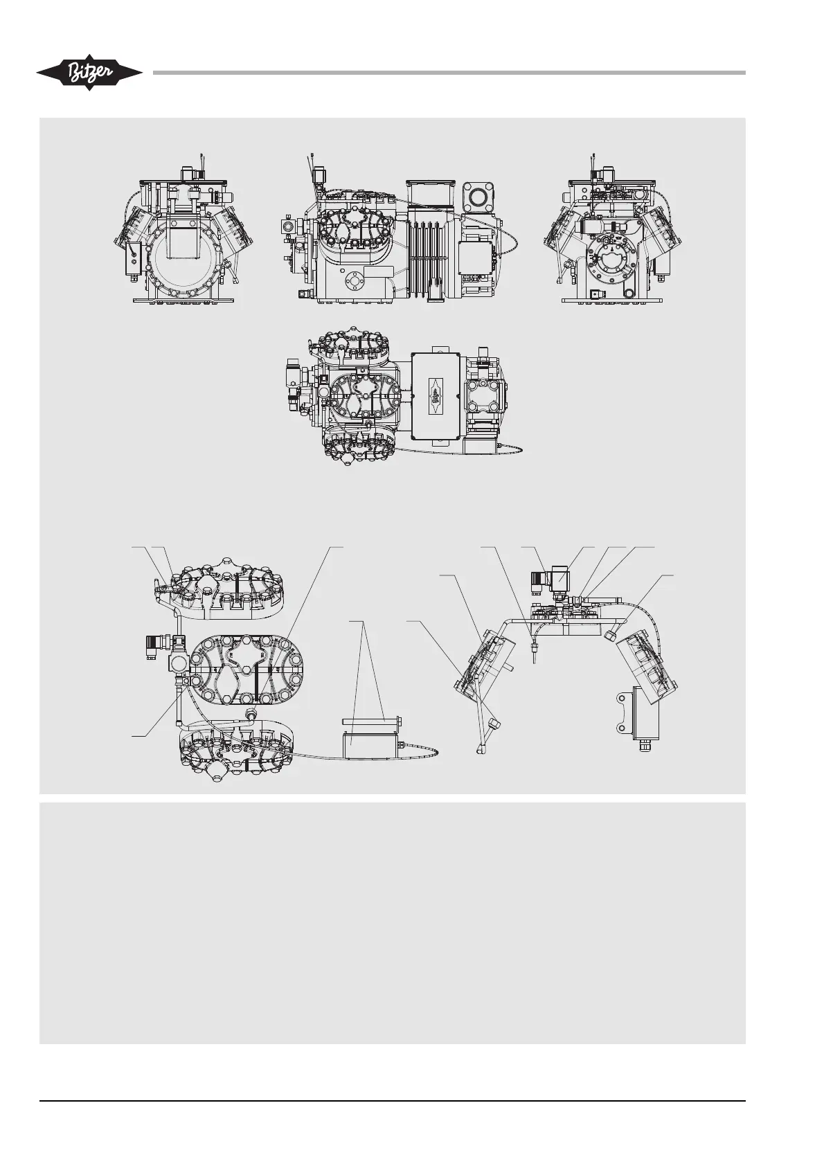
Abb. 6c Einbaupositionen des Einspritz-
ventils: 6JE-25(Y) .. 6FE-44(Y)
Fig. 6c Mounting position of the injection
valve: 6JE-25(Y) .. 6FE-44(Y)
Fig. 6c Position de montage de la vanne
d'injection: 6JE-25(Y) .. 6FE-44(Y)
Darstellung des Einspritzventils (5) mit
Magnetspule (B)
3 Druckgastemperaturfühler
4 Einspritzdüse
4a Einspritzdüse
5 Einspritzventil
5a Befestigungsblech (2 verschiedene)
5b Rohrschelle
5c Schraube M6x12
5d Mutter M6
A Zylinderkopfschraube
B Magnetspule
C Steuergerät mit Halterung und verlän-
gerten Motordeckelschrauben
Vergrößerte Detaildarstellung ohne
Verdichtergehäuse
Enlarged detail view without compressor
housing
Représentation en detail élargie sans corps
du compresseur
Injection valve (5) shown with solenoid
coil (B)
3 Discharge gas temperature sensor
4 Injection nozzle
4a Injection nozzle
5 Injection valve
5a Fixing plate (2 different types)
5b Pipe clamp
5c Screw M6x12
5d Nut M6
A Cylinder head screw
B Solenoid coil
C Controle device with fixture and longer
motor cover screws
Représentation de la vanne d'injection (5)
avec la bobine magnétique (B)
3 Sonde du temp. du gaz de refoulement
4 Gicleur d'injection
4a Gicleur d'injection
5 Vanne d'injection
5a Tôle de fixation (2 modéles différents)
5b Collier d'attache
5c Vis M6x12
5d Ecrou M6
A Vis de tête de culasse
B Bobine magnétique
C Dispositif de commande avec fixage et vis
du couvercle du moteur rallongées
6JE-25(Y) .. 6FE-44(Y)