EasyManua.ls Logo

Bitzer SE-E1

Bitzer SE-E1
36 pages
To Next Page IconTo Next Page
Loading...
ST-120-3
Protection devices for screw compressors of HS.-, CS.-, OS.-, VSK series
Translation of the original document
English....................................................................................................................................................... 2
Schutzgeräte für Schraubenverdichter der HS.-, CS.-, OS.-, und VSK-Serie
Originaldokument
Deutsch ..................................................................................................................................................... 14
Dispositifs de protection pour des compresseurs à vis des séries HS.-, CS.-, OS.-, et VSK
Traduction du document original
Français..................................................................................................................................................... 25
SE-E1
SE-E3
SE-B2
OFC
Electrically skilled installer
Elektrisch unterwiesener Monteur
Monteur habilité

Table of Contents

Question and Answer IconNeed help?

Do you have a question about the Bitzer SE-E1 and is the answer not in the manual?

Bitzer SE-E1 Specifications

General IconGeneral
Housing materialPlastic
Protection functionsphase failure, locked rotor
Operating temperature-20°C to +60°C
MountingDIN rail
Weight0.2 kg

Summary

Introduction to BITZER Protection Devices

Safety Information and Precautions

Authorized Staff for Operation

Work on protection devices, compressors, and refrigeration systems must be performed by qualified and authorized staff.

Understanding Residual Risks

Compressors and accessories present unavoidable residual risks; users must read this document carefully.

Strict Adherence to Safety References

Instructions intended to prevent hazards and must be stringently observed.

Overview and Technical Data

Technical Data Summary

Provides a summary of monitoring functions and assigns protection devices to compressor series.

SE-E1 and SE-E3 Protection Devices

SE-E1 and SE-E3 Monitoring Functions

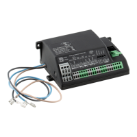
Covers monitoring functions like temperature, rotation direction, and phase failure for SE-E1 and SE-E3.

SE-B2 Protection Device

SE-B2 Monitoring Functions

Details the oil flow monitoring function for SE-B2, used with time relay and electrolytic capacitor.

OFC Protection Device

Electrical Connection and Wiring

Schematic Wiring Diagrams Overview

Shows electrical connections for protection devices in terminal boxes or switch cabinets.

CS Series Connection: SE-E1 SE-E3

Example wiring diagram for connecting SE-E1/SE-E3 to CS series compressors.

HS.53-HS.74 Connection: SE-E1 SE-E3 with SE-B2

Example wiring for SE-E1/SE-E3 and SE-B2 in terminal box and switch cabinet for HS.53..HS.74.

HS.53-HS.74 Connection: SE-E1 SE-E3 with OFC

Example wiring for SE-E1/SE-E3 and OFC in terminal box and switch cabinet for HS.53..HS.74.

HS.85 Connection: SE-E1 SE-E3 with two SE-B2

Example wiring for SE-E1/SE-E3 and two SE-B2 in terminal box and switch cabinet for HS.85.

HS.85 Connection: SE-E1 SE-E3 with two SE-B2 and OFC

Example wiring for SE-E1/SE-E3, two SE-B2, and one OFC in switch cabinet for HS.85.

Related product manuals