Do you have a question about the Bitzer SE-B2 and is the answer not in the manual?
Qualifications and training required for personnel working on protection devices and refrigeration systems.
Highlights potential hazards associated with compressors and electronic accessories, emphasizing document reading.
Instructions to prevent hazards, requiring strict observance for safe operation.
Summary of monitoring functions and compressor series compatibility for protection devices.
Details on monitoring functions like temperature, rotation direction, and phase failure for SE-E1 and SE-E3 devices.
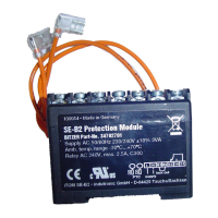
Explains the use of SE-B2 for oil flow monitoring in semi-hermetic and open drive screw compressors.
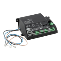
Describes the mounting options for the OFC protection device, typically in a switch cabinet.
Specifies the time delays for the OFC device during start procedure and operation.
Guidance on connecting the OFC device for oil flow monitoring, referencing wiring diagrams.
Procedure for resetting the OFC device after a fault condition has occurred.
Wiring diagram for connecting SE-E1/SE-E3 protection devices in CS series compressors.
Wiring diagram for SE-E1/SE-E3 with SE-B2 in HS.53..HS.74 compressors.
Wiring diagram for SE-E1/SE-E3 with OFC in HS.53..HS.74 compressors.
Wiring diagram for SE-E1/SE-E3 with two SE-B2 in HS.85 compressors.
Wiring diagram for SE-E1/SE-E3 with two SE-B2 and OFC in HS.85 compressors.
| Brand | Bitzer |
|---|---|
| Model | SE-B2 |
| Application | Refrigeration systems |
| Pressure range | Not applicable |
| Protection class | IP54 |
| Function | Monitoring and protection |
| Monitored parameters | Oil level |
| Alarm output | Relay output |
| Supply voltage | AC 24 - 240V, DC 24V |
| Mounting | Compressor housing |
| Dimensions | Varies depending on model configuration |
| Certifications | CE |
| Features | Adjustable time delay, LED status indication |