3
tige Voraussetzung für eine weitge-
hend betriebssichere Gestaltung der
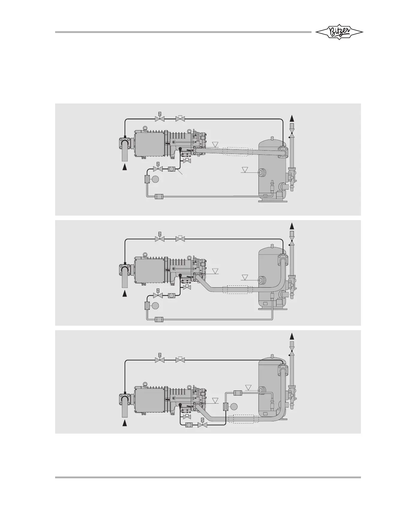
Anlage ist die Überhöhung der Öllei-
tung auf Oberkante Ölschauglas.
Zudem muss die Druckgasleitung
zunächst nach unten geführt werden
(siehe auch Kapitel 2.2).
tion to ensure largely reliable plant
operation is to raise the oil injection to
the level of the top of the oil sight
glass. Moreover the discharge gas
line should initially run downwards (as
shown in chapter 2.2).
pour une réalisation relativement fiable
est le rehaussement de la conduite d'hui-
le jusqu'au bord supérieur du voyant
d'huile. En plus de cela, la conduite de
refoulement doit d'abord être dirigée vers
le bas (voir également chapitre 2.2).
ST-121-1
Abb. 1 Anordnung von Ölabscheider,
Druckgas- und Öleinspritzleitung
1 Stillstands-Bypass
2 Schwingungsdämpfer (bei
Bedarf)
Fig. 1 Layout of oil separator, discharge
gas and oil injection pipe lines
1 Standstill by-pass
2 Vibration damper (if required)
Fig. 1 Disposition du séparateur d’huile et des
conduites de refoulement et d'injection
1 Bipasse d'arrêt
2 Amortisseur de vibrations (si néces-
saire)