Semiconductors
Purely semiconductor devices (suchas diodes and transis-
tors) will produce signatures with straight lines and bends.
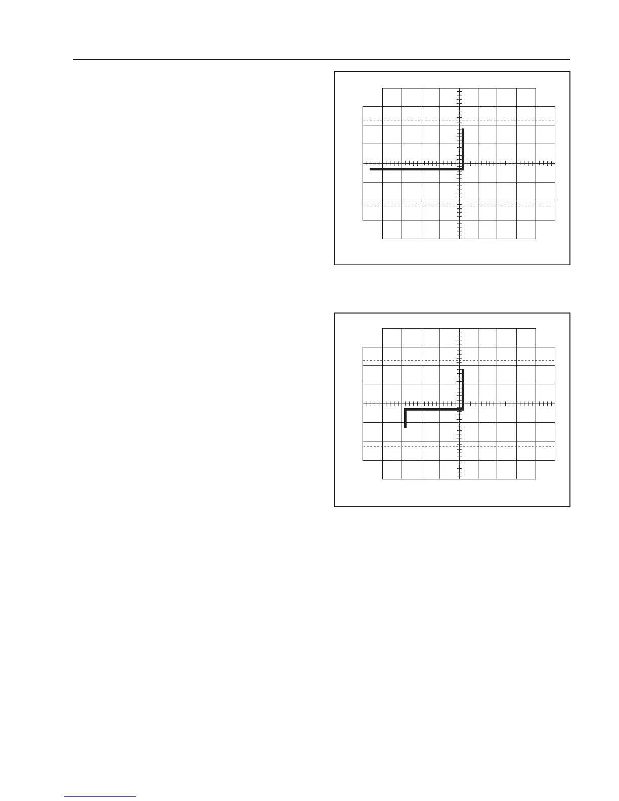
Typical diode junctions produce a single bend with a hori-
zontal and vertical line as shown in Fig. 9. Zener diodes
produce a double bend with two vertical and one horizontal
line as shown in Fig. 10 (valueis determined by the distance
of the leftmost vertical component from the center gradu-
ation on the CRT). The maximum Zener voltage observable
on this feature is about 15 V. It is also possible to test
transistors and IC’s by testing one pair of pins at a time.
NOTE
When testing diodes it is important to
connect the diode’s cathode to the white
COMP TEST jack and the anode to the
GND jack.Reversingthepolarity will not
damage the device but the horizontal and
vertical components of the signature will
appear in different quadrants of the
display.
To test semiconductors, insert the diode’s or transistor’s
leads (only two at a time) into the COMP TEST and GND
jacks (make sure that the leads touch the metal walls inside
the jacks). To test in-circuit or to test IC’s or devices with
leads too short to insert into the COMP TESTand GND
jacks, a pair of test leads can be used to connect the COMP
TEST and GND jacks to the component(s).
Combinations of Components
Using the component test feature it is also possible to
observe the signatures of combinations of components.
Combinations cause signatures that are a combination of the
individual signatures for each component. For example, a
signature for a resistor and capacitor in parallel will produce
a signature with the ellipse of the capacitor but the resistor
would cause the ellipse to be at an angle (determined by the
value of the resistor). When testing combinations of compo-
nents it is important to make sure that all the components
being connected are within measurement range.
In-CircuitTesting
The component test feature can be very effective in locat-
ing defective components in-circuit, especially if a “known
good” piece of equipment is available for reference. Com-
pare the signatures from the equipment under test with
signatures from identical points in the reference unit. When
signaturesare identical or very similar,thetestedcomponent
is good. When signatures are distinctively different, the
tested component is probably defective.
100
90
10
0
Silicon Diode
Fig. 9. Typical P-N Junction Signature.
100
90
10
0
10 V Zener Diode
Fig. 10. Typical Zener Signature.
OPERATING INSTRUCTIONS
19
 Loading...