CONTROLS AND INDICATORS
GENERAL FUNCTION CONTROLS
1. ON Indicator. Lights when oscilloscope is “on”.
2. 2160A Only. POWER/Scale ILLUMination Con-
trol. Clockwise rotation from OFF position turns os-
cilloscope “on”. Further clockwise rotation increases
amount of graticule illumination.
3. 1541D Only. POWER Pushbutton. Turns oscillo-
scope “on” and “off”.
4. INTENSITY Control. Adjusts brightness of trace.
5. TRACE ROTATION Control. Adjusts to maintain
trace at a horizontal position.
6. FOCUS Control. Adjusts trace focus.
7. 2160A Only. COMPonent TEST Pushbutton. With
pushbutton set to “in” position, Component Testmode
is enabled. Normal scope operation is enabled with
pushbutton in “out” position.
8. 2160A Only. COMPonent TEST Jack. “Banana”-
type HI-side input jack for connection to component
in Component Test operating mode.
9. GND Terminal. Oscilloscope chassis ground
jack, and earth ground via three-wire ac power cord.
On Model 2160A, also serves as LO-side Component
Test jack.
10. CAL Terminal. Terminal provides 2 V p-p, 1 kHz
(nominal) square wave signal. This signal is useful for
checking probe compensation adjustment, as well as
providing a rough check of vertical calibration.
11. 2160A Only. BEAM FINDPushbutton.Momentary-
contact pushbutton speeds setup of trace positioning
by bringing the beam into graticule area; operates
independently of other display controls.
VERTICAL CONTROLS
12. VERTical MODE Switch. Selects vertical display
mode. Four-position lever switch with the following
positions:
CH1:
Displays the channel 1 signal by itself.
CH2/X-Y:
CH2: displays the channel 2 signal by itself.
X-Y: used in conjunction with the X-Y control and
Trigger SOURCE switch to enable X-Y display
mode.
DUAL:
Displays the channel 1 and channel 2 signals simul-
taneously. Dual-trace mode may be either alternate
or chopped sweep; see the description under
HOLDOFF/PULL CHOP control.
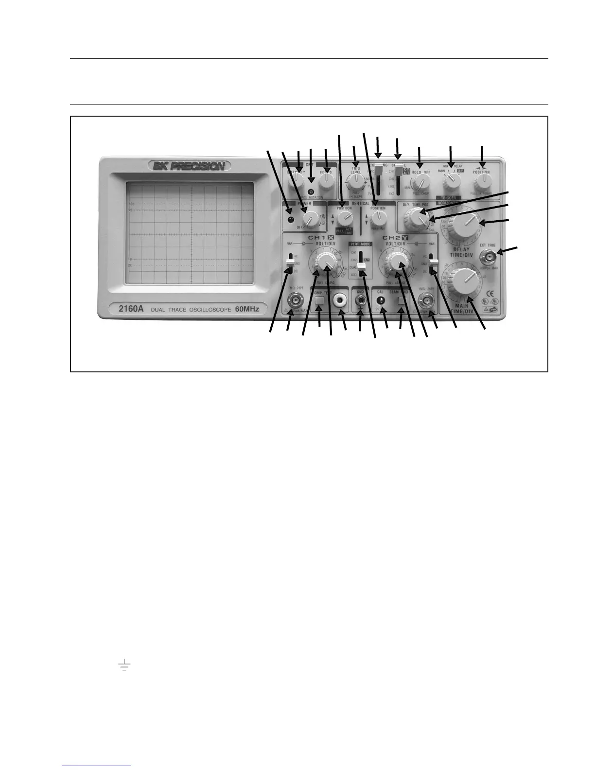
Fig. 1. Model 2160A Controls and Indicators.
7
2
6
1
4
17
33
18
32
31
30
28
27
26
25
24
34
23
22
21
20
19
11
10
12
9
8
16
7
15
14
13
5
 Loading...