9
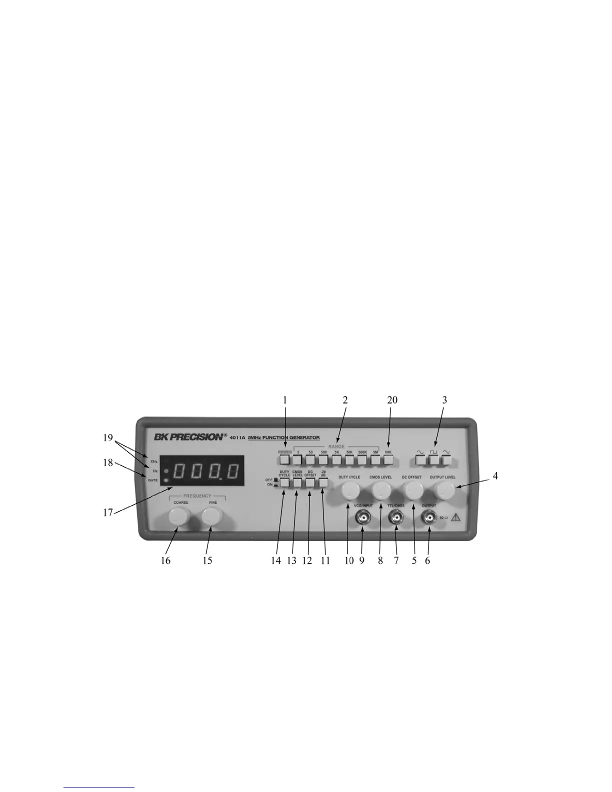
Figure 1. Model 4011A Controls and Indicators.
13. CMOS LEVEL Switch. When engaged, changes
the TTL signal to CMOS signal at the TTL/CMOS
jack.
14. DUTY CYCLE Switch. When engaged, enables
operation of DUTY CYCLE control (10).
15. FINE FREQUENCY Control. Vernier adjustment
of the output frequency for ease of setting frequency.
16. COARSE FREQUENCY Control. Coarse
adjustment of the output frequency from 0.1 to 1
times the selected range.
17. COUNTER DISPLAY. Displays frequency of internally
generated waveform.
18. GATE LED. Indicates when the frequency counter display is
updated. When the 50K through 5M ranges are selected, the
LED will flash 10 times per second (every 0.1 seconds).
When the 50 through 5K ranges are selected, the LED will
flash once every second and when the 5 range is selected, the
LED will flash every 10 seconds. As the LED turns off, the
display is updated.
19. Hz and KHz LED. Indicates whether the counter is reading
in Hz or kHz.
20 Inverter Switch