10
OPERATING INSTRUCTIONS
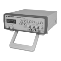
The B+K Precision Model 4011A Function Generator is a
versatile instrument, capable of producing a variety of output
waveforms over a broad range of frequencies. To gain a working
familiarity with the unit, it is recommended that it be connected
initially to an oscilloscope, so that the effects of the various controls
on the output waveforms can be observed. Use this manual as
required for reference until becoming accustomed to the operating
procedures.
FREQUENCY AND WAVEFORM SELECTION
l. Initially, verify that the DUTY CYCLE (14), CMOS LEVEL
(13), DC OFFSET (12), -20dB (11) switches are in the OUT
position (released). This will produce a symmetrical waveform
unaffected by the other controls.
2. Plug the unit into an appropriate power source and turn it on by
engaging the POWER switch (1).
3. Select the desired waveform (SINE, SQUARE, or TRIANGLE)
by engaging one of the FUNCTION switches (3). Phase
relationships of the waveforms are shown in Fig. 2.
4. Select the frequency of the waveform by engaging one of the
RANGE switches (2). The output frequency is displayed, along
with the appropriate measurement units, kHz or Hz (19), on the
LED display.
5. Rotate the COARSE (16) frequency control to quickly set the
output frequency to the approximate desired value. The FINE
(15) frequency control can then be used to easily set the output
to the specific desired value. The frequency selected is available
at the OUTPUT jack (6). In addition, a digital signal, either TTL
or CMOS is available at the TTL/CMOS jack (7) (refer to the
“TTL/CMOS OUTPUT” section of this manual).
6. Adjust the amplitude of the output as desired using the
OUTPUT LEVEL control (4). Rotation of this control
varies the amplitude from maximum to 20dB below
maximum. An additional attenuation of -20dB is
available by pushing in the -20dB switch (11). The
attenuation factors can be combined for a total of -40dB.
The maximum si