L1
S
N
Z1
1~
M
T
S1
NCNOC
Volt
2 x 2,5mm
2
120-127V / 60Hz
220V-230V / 50-60Hz
10m Max
S = Interruptor/Interruptor/Switch
Z1 = Capacitor supresor/Capacitor
de supressão/Capacitor supressor
T = Protección termal/Proteção
térmica/Thermal protector
M = Motor
S1 = Interruptor de presión/Interruptor
de pressão/Pressure switch
FIG. F
FIG. G
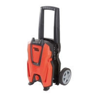
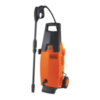
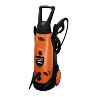
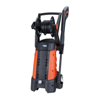
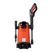
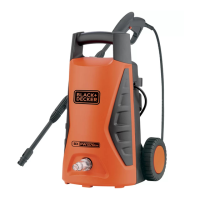
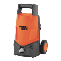
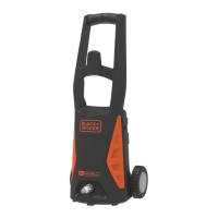
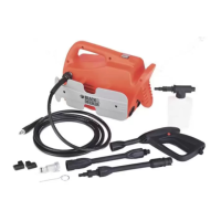
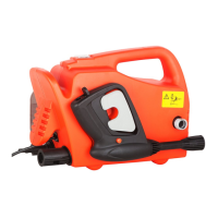
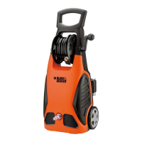
Nota: Los diagramas son referenciales, el producto puede cambiar en su apariencia o especificación sin previo aviso.
Nota: Os Diagramas são referenciais, o produto ou sua especificação pode ser ligeiramente diferente sem aviso prévio.
Note: The diagrams are for reference, the product may change in appearance or specifications without notice.
 Loading...