724-746-5500 | blackbox.com
Page 11
CONFIGURATION
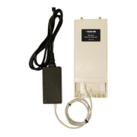
1.3.2 External 48 VDC power supply
Input:
• Rated voltage: 36–60 VDC
• Rated current: 0.25 A DC
• 3-pin locking connector, 3.5 mm pitch
• Transient over-voltage protection, 100VDC at 2 ms
Output:
• Rated voltage: 5 VDC ± 5%, 5W
• Rated current; 1 A DC
• 6-inch cable terminated with 2.5 mm barrel plug, center positive
2. CONFIGURATION
You can configure the LB512A-KIT through the hardware configuration via DIP
switches.
2.1 HARDWARE (DIP-SWITCH) CONFIGURATION
To use DIP-switch configuration you must first set the DIP switches to a position other
than all OFF or all ON before powering-up the LB512A-KIT. When all the DIP switches
are set to any position other than all OFF or all ON the LB512A-KIT will operate in
hardware (DIP-switch)-configuration mode. In DIP-switch-configuration mode the
LB512A-KIT will read the DIP-switch settings during system startup and configure itself
according to the switch settings. Once you power-up the LB512A-KIT in DIP-switch
mode, it will operate in DIP-switch mode until powered down. When operating in DIP-
The external DC adaptor shall be a listed limited power source that
incorporates a disconnect device and shall be positioned within
easy reach of the operator. The interconnecting cables shall be
rated for the proper voltage, current, anticipated temperature,
flammability, and mechanical serviceability.
CAUTION
724-746-5500 | blackbox.com
Page 18
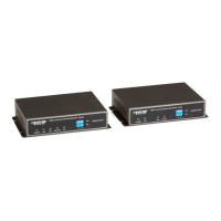
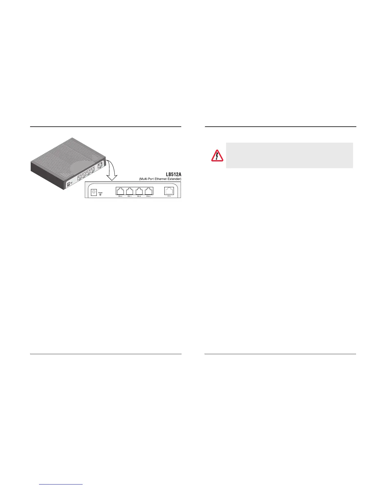
Black Box Long Range Ethernet Extender
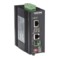
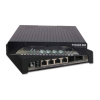
Figure 4.
LB512A-KIT rear panel
3.1 CONNECTING THE LINE INTERFACE
The LB512A-KIT supports communication between two DTE devices as follows.
Using 24 AWG (0.5 mm) wire up to:
• 18,000 feet (5.48 km) at 192 kbps
• 11,000 feet (3.5 km) at 5696 kbps
Two things are essential:
1. These units work in pairs. Both units at the end of the twisted pair link span must
b
e set for the same DTE rate—one unit set as Local (L), the other as Remote (R).
2. To function properly, the LB512A-KIT needs one twisted pair of metallic wire. This
twisted pair must be unconditioned, dry, metallic wire, between 19 (0.9mm) and 26
AWG (0.4mm) (the higher number gauges will limit distance). Standard dial-up
telephone circuits, or leased circuits that run through signal equalization equip-
ment, or standard, flat modular telephone type cable, are not acceptable.
The RJ-45 Li
ne connector on the LB512A-KIT’s twisted pair interface is polarity insen-
sitive and is wired for a two-wire interface.