724-746-5500 | blackbox.com
Page 17
• noise margin: The maximum tolerable increase in external noise power that still
allows for BER of less than 1x 10–
7
.
• e
rror counters: The following error counters are available:
-CRC
-LOSW (Loss of Sync Word)
2.4.2 Help Commands
The following commands are provided to help the user find the correct command:
• he
lp: Lists all the commands that the console recognizes.
2.4.3 Example command line interface session
LB512A-KIT Command Shell
Password:
LB512A-KIT> status
configuration:
link mode: co
link rate: 5696
line probe: disabled
status:
actual rate: 0
loss of signal: unavailable
noise margin: 0
snr: 0
sync state: out of sync
link state: idle
error counters:
crc: 0
losw: 0
LB512A-KIT> exit
NOTE: The line probe feature is a future product enhancement.
3. INSTALLATION
Once the LB512A-KIT is properly configured, it is ready to connect to the Line interface
and to the power source. This section explains how to make these connections.
724-746-5500 | blackbox.com
Page 12
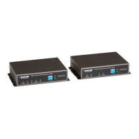
Black Box Long Range Ethernet Extender
switch mode, you cannot change any configuration settings. Table 1 lists the LB512A-
KIT’s configurable parameters.
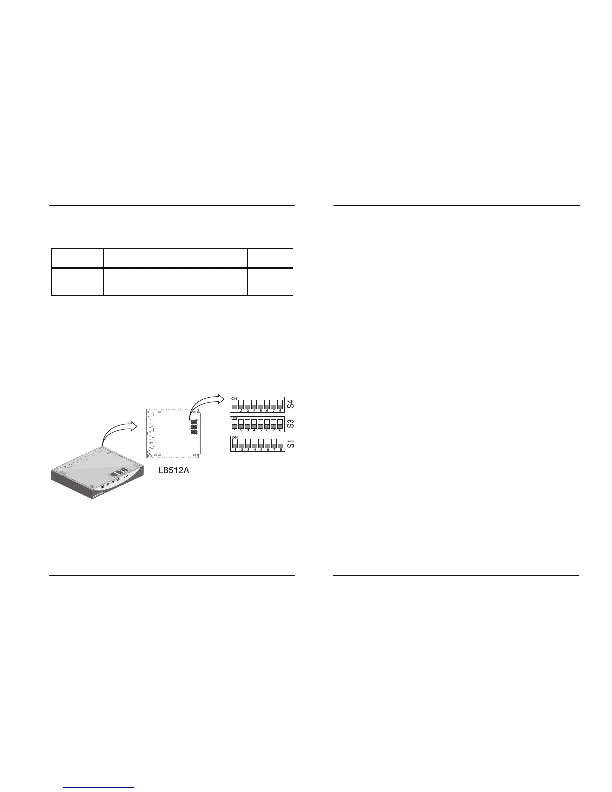
2.2 CONFIGURING THE DIP-SWITCHES
The LB512A-KIT is equipped with three sets of DIP switches, which you can use to
configure the extender for a broad range of applications. This section describes switch
locations and discusses the configuration options available.
NOTE: By default, the DIP switches are all set to “OFF”. The default configuration for
th
e LB512A-KIT is 89 timeslots (5695 kpbs).
The three sets of DIP switches are externally accessible from the underside of the
L
B512A-KIT (see Figure 3).
Figure 3.
Underside of LB512A-KIT showing location of DIP switches
Table 1:
LB512A-KIT configurable parameters
Parameter Description
Possible
Va
lues
Data
R
ate/Timeslots
Defines the number of timeslots. The data rate
is calculated by the equation:
data rate = timeslots x 64k
1-72
timeslots