724-746-5500 | blackbox.com
Page 12
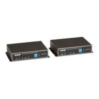
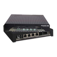
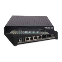
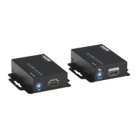
VDSL2 Line Power Ethernet Extender Kit
4. DIP Switches
Table 4-1 shows the definition of the DIP Switches. Select the switches for optimal configuration.
SW-1: CO/Remote
Off: VDSL2 Line Power Ethernet Extender will act as at the Central Office (Master) side.
On: VDSL2 Line Power Ethernet Extender will act as at the Customer Premise Equipment (CPE) or Remote side.
SW-2: Mode for impulse noise protection
Off: Interleaved mode provides impulse noise protection for any impulse noise with a duration less than 250 µs.
Interleaved mode has a maximum end-to-end latency of 10 ms. Interleaved mode is the default mode.
On: Fast mode guarantees a minimum end-to-end latency less than 1 ms.
SW-3: Rate limit control
Off: Line rate limited to 50-/20-Mbps.
On: Provides up to 100-/60-Mbps line rate for distances up to 500 feet (152.4 m).
SW-4: Signal to Noise Ratio (SNR)
Off: Higher SNR margin (9 dB) will result in fewer errors with a more stable VDSL link.
On: Original and normal channel noise protection with 6 dB SNR.
Table 4-1. DIP switches and their functions.
DIP Switches SW-1 SW-2 SW-3 SW-4
Definition CO/Remote Impulse Noise
Protection Mode
Data Rate SNR
Off CO Interleaved 50/20 Mbps 9 dB
On Remote Fast Full Rate 6 dB
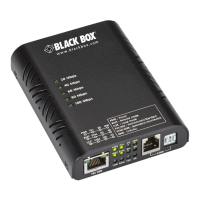
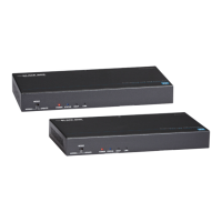
VDSL2 Line Power Ethernet
Extender (Master)
VDSL2 Line Power Ethernet
Extender (Slave)
Figure 4-1. Default value of DIP switches.