EasyManua.ls Logo

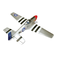
Black Horse Model Mustang P51 User Manual

Black Horse Model Mustang P51
34 pages
To Next Page IconTo Next Page
Page #1 background imageLoading...
Page #1 background image
SPECIFICATION
Wingspan : 1.560 mm 61.42 in.
Length : 1.360 mm 53.54 in.
Weight : 3.2 kg 7.04 Lbs.
Radio : 06 channels.
Servo : 07 Servos+2 servos Retract (HITEC HS-75BB)
Engine : 61 Cu.in 2 Stroke.
91 Cu.in 4 Stroke.
Instruction Manual book
Made in Vietnam.
Item code BH33.

Other manuals for Black Horse Model Mustang P51

Question and Answer IconNeed help?

Do you have a question about the Black Horse Model Mustang P51 and is the answer not in the manual?

Black Horse Model Mustang P51 Specifications

General IconGeneral
BrandBlack Horse Model
ModelMustang P51
CategoryToy
LanguageEnglish

Summary

Mustang P51 Specifications

Safety Warning and Disclaimer

Tools and Supplies Needed

Parts Listing

Important Notes

Safety Precautions

Film Covering Correction

Guidance on correcting minor film creases or warps using heat and gentle manipulation.

Construction Accuracy

Emphasis on careful, accurate work for a strong and well-flying model.

Screw Loosening Prevention

Applying white glue to holes before inserting self-tapping screws to prevent loosening.

Pre-Construction Advice

Installing the Aileron Servos

Aileron Servo Preparation

Installing rubber grommets and brass eyelets onto servos and preparing the wing surface.

Aileron Servo Lead Routing

Using a thread to guide the servo lead through the wing and removing the thread.

Aileron Servo Mounting Holes

Drilling pilot holes for the servo mounting screws.

Installing the Aileron Control Horn

Aileron Control Horn Assembly

Attaching the control horn to the aileron using provided hardware.

Control Horn Covering Removal

Carefully removing covering from the wing surface to mount the control horn.

Installing the Aileron Linkages

Linkage Clevis and Wire Connection

Connecting the aileron linkage clevis to the threaded wire and control horn.

Servo Centering and Arm Installation

Centering the servo and installing the servo arm perpendicular to the servo.

Aileron Pushrod Connection

Servo Arm Modification and Pushrod Bend

Modifying the servo arm and bending the pushrod wire for connection.

Pushrod Securing

Securing the pushrod to the servo arm using a snap keeper and screw.

Installing Flap Servos and Control Horns

Installing Retractable Landing Gear

Landing Gear Assembly and Mounting

Landing Gear Mounting Details

Installing Landing Gear Servos

Retractable Landing Gear Final Steps

Installing the Engine Mount

Fuel Tank Assembly and Stopper

Fuel Line Preparation and Bending

Cutting and bending fuel lines for pickup, vent, and fueling valve.

Fuel Tank Installation

Fuel Line Routing and Tank Securing

Routing fuel lines through firewall, securing tank with sealant, and temporary placement.

Installing the Engine

Throttle Pushrod Connection

Connecting the 'Z' bend throttle pushrod to the engine's throttle arm.

Cowling Installation - Part 1

Cowling Installation - Part 2

Muffler and Fuel Line Connections

Installing muffler, making cowl cutouts, and connecting fuel lines to carburetor and valve.

Installing the Spinner

Installing Fuselage Servos

Installing Receiver and Battery

Receiver and Battery Securing

Wrapping receiver and battery in foam, securing with tape, and positioning behind fuel tank.

Horizontal Stabilizer Installation

Stabilizer Mounting Area Preparation

Cutting away fuselage covering for the horizontal stabilizer mounting area.

Horizontal Stabilizer Fitting and Alignment

Stabilizer Marking and Covering Removal

Marking stabilizer and carefully removing covering based on vertical stabilizer shape.

Stabilizer Parallellism Check

Ensuring stabilizer is parallel to wing, sanding opening if needed.

Elevator Control Horn Installation

Control Horn Attachment Method

Attaching elevator control horn similarly to aileron control horn.

Stabilizer Gluing and Securing

Applying epoxy to stabilizer and fuselage mounting areas, securing with pins or tape.

Elevator Pushrod Installation

Elevator Pushrod Linkage

Connecting elevator pushrods to control horns and servos.

Vertical Stabilizer Mounting

Rudder Placement and Marking

Placing rudder into fuselage and marking its shape on the vertical stabilizer.

Tail Wheel Bracket Mounting

Vertical Stabilizer Fitting and Gluing

Rudder Covering Removal and Gluing

Removing rudder covering and applying epoxy for secure attachment.

Vertical Stabilizer Hinge Installation

Rudder Hinge CA Installation

Installing CA hinges for the rudder by cutting covering and applying glue.

Vertical Stabilizer Final Gluing

Applying epoxy to stabilizer mounting platform and lower rudder hinge, securing and allowing to cure.

Control Horn and Pushrod Installation

Rudder Pushrod Installation

Rudder Pushrod and Servo Connection

Final Servo Connections

Throttle Servo Installation

Throttle Servo Connector Securing

Securing the adjustable metal servo connector with CA glue to prevent loosening.

Installing the Radio Switch

Receiver and Battery Installation

Receiver and Battery Securing

Wrapping receiver and battery in foam, securing with tape, and positioning behind fuel tank.

Retractable Servo Installation

Joining the Wing Halves

Wing Attachment to Fuselage

Balancing the Airplane

Center of Gravity (CG) Location

CG is 135mm back from wing leading edge. Adjustments may be needed for optimal flight.

Balancing Procedure

Marking balance points, lifting plane with fingers, and checking for tail or nose heaviness.

Control Throws Setup

Recommended Control Throw Values

Specific up/down throws for ailerons, flap, elevator, and rudder.
Pre-Flight Checks

Related product manuals