TOOLS REQUIRED: 7/16”, 1/2” and 9/16" sockets and ratchets, block(s) of wood (minimum of 6” tall).
Refer to the parts list on page 9.
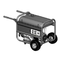
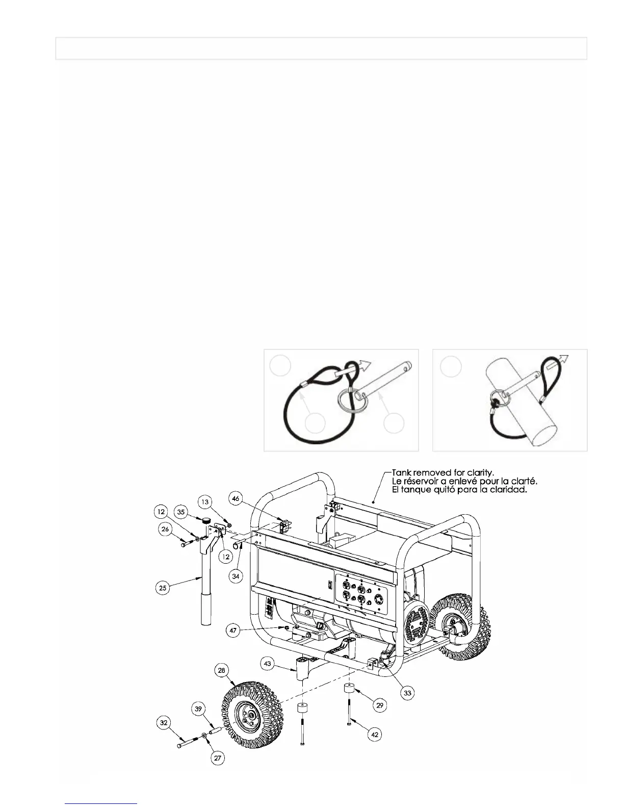
WHEEL INSTALLATION
1.Block up end of generator opposite the fuel tank cap to install wheel kit.
2.Insert wheel spacer (item 39) into the center of the wheel (item 28).
3.Slide 3/8 x 4.25” bolt (item 32) and 3/8 washer (item 27) through the wheel (item 28), then through the wheel bracket on the
carrier, with the offset side of the wheel hub against the wheel bracket.
4.Thread 3/8 nyloc nut (item 33) onto the bolt and tighten to securely clamp the wheel assembly to the carrier.
5.Repeat above instructions for the remaining wheel.
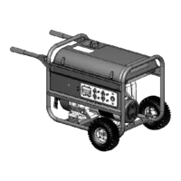
FOOT INSTALLATION
1.Blocking up the engine side of the generator, place the foot bracket (item 43) under the carrier channel. Thread a 5/16-18 x 4”
bolt (item 42) with a rubber foot (item 29) through the mounting holes and thread a 5/16 flange nut (item 47) to the bolt to
secure the foot bracket to the carrier. Caution: Do not over tighten so that the rubber foot material collapses.
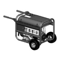
HANDLE INSTALLATION
1.Place handle (item 25) and spacer (item 46) on carrier on same end as feet, as shown in the diagram.
2.Slide 5/16 x 2.25” bolt (item 26) and 5/16 washers (item 12) through handle and handle bracket as shown in diagram and
secure with 5/16” nyloc nut (item 13). Tighten until handle is securely clamped to the carrier.
3.Apply aerosol hairspray or similar adhesive to the handle (item 25), and then slide the handle grip (item 40) onto the handle.
The aerosol hairspray will allow for easier assembly and will adhere the grip to the handle.
4.Insert cap (item 35) into end of handle (item 25).
5.Repeat above instructions for the remaining handle.
LOCKING HANDLE
1.Attach the lanyards (item 30) to the release
pins (item 34) and carrier as shown in the
illustration.
2. To lock the handle (item 25) in the extended
position, align the holes in the handle brackets
with the holes in the carrier brackets and insert
the release pins (item 34).
English
PORTABILITY KIT INSTALLATION
1
2
3430