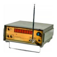
DISPLAYS/INDICATORS
The
gate
time
LED
(4)
is lit
for
the duration of each
measurement
period.
The
kHz
(10)
and MHz
('11)
LED's indicate the
scale factor
of
the
display. The
display
(12)
has leading
zero suppression
(for
power
conservation) and
auto-
matic
decimal
point
location.
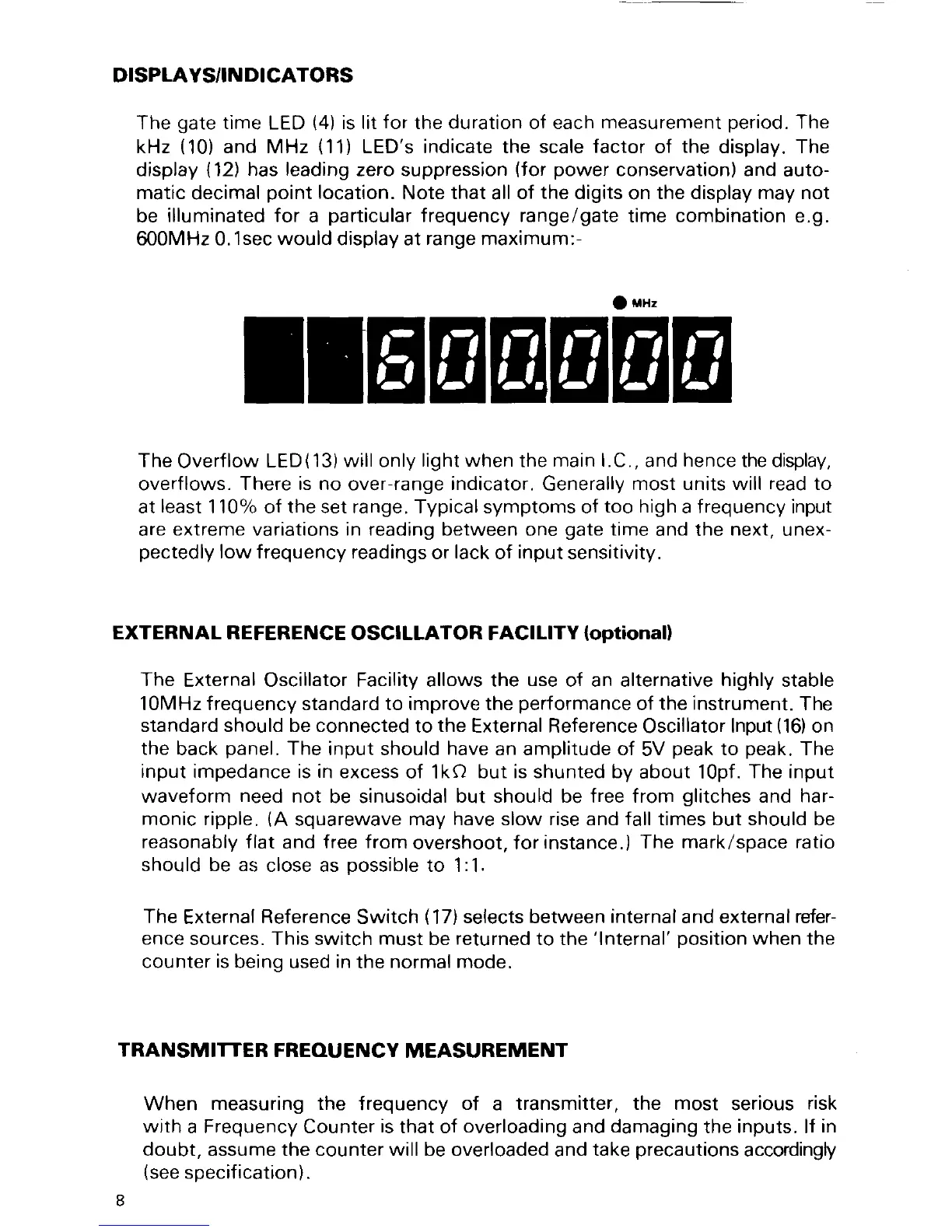
Note
that
all
of
the
digits
on
the display may not
be
illuminated for
a
particular
frequency range/gate
time
combination
e.g.
600MHz 0.1sec
would
display at
range maximum:-
O
mxz
IIEENENE
The
Overflow
LED(13)willonly
light when
the
main LC
,
and
hence
the display,
overflows.
There is no
over-range
indicator.
Generally
most units will
read
to
at
least
11oo/o of the set range. Typical symptoms of
too high
a f
requency
input
are
extreme
variations
in reading
between one
gate
time
and the
next,
unex-
pectedly
low frequency readings
or
lack
of
input
sensitivity.
EXTERNAL REFERENCE
OSCILLATOR FACILITY
{optional)
The
External Oscillator Facility allows the
use
of an alternative
highly
stable
10MHz frequency standard to improve the
performance
of
the instrument.
The
standard should be connected
to
the
External Reference
Oscillator
lnput
(16)
on
the
back
panel.
The
input should
have
an amplitude of
5V
peak
to
peak.
The
input
impedance is
in
excess
of 1ka but
is shunted by
about 1Opf.
The input
waveform
need
not
be sinusoidal
but should be free from
glitches
and har-
monic ripple.
(A
squarewave
may have slow rise and fall times but should be
reasonably flat
and
free fromovershoot.forinstance.)
The mark/space
ratio
should be as
close as
possible
to 1:1.
The
External
Reference
Switch
(17)
selects between
internal
and external
refer-
ence
sources. This switch
must
be
returned
to the
'lnternal'
oosition
when
the
counter
is
being
used
in
the
normal mode.
TRANSMITTER
FREOUENCY
MEASUREMENT
When
measuring the
frequency
of
a
transmitter, the most
serious
risk
with
a Frequency Counter
is
that of
overloading
and
damaging
the inputs. lf
in
doubt, assume the counter will be overloaded
and
take
precautions
accordingly
(see
specif
ication).
I
 Loading...