Page 3Rev. 032318 DiscountRamps.com • 1-888-651-3431
Assembly
Note: Bolts and nuts should be tightened by hand rst; after all parts have been assembled, go back
and tighten all hardware with a wrench.
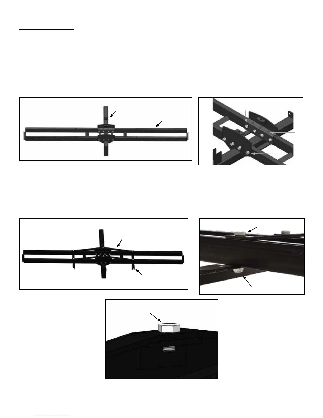
Step 1. Place the hitch tube (L) on a solid work surface with the mounting brackets facing upward.
Place the platform pieces (I) across the hitch tube, positioned between the two middle brackets.
(Make sure the ramp brackets are facing up.) Align the holes on the platform and L-plates (Q), secure
with eight 3/8"x1-3/4" bolts (C) and 3/8" lock nuts (F). NOTE: The bolts are inserted from the inside
out.
(1a)
(1b)
L
C
Q
F
I
Step 2. Place the cross bars (P) on top of the platform and the support brackets (H) beneath the
platform. (The rubber-coated ends of the support brackets should be towards the front of the carrier.)
Align the holes and secure with four 3/8"x2-3/4" bolts (B), four 3/8" lock nuts (F) and two M10x16
bolts (D).
(2a)
(2b)
P
H
B
F
D


 To Next Page