ENGLISH
8
(Original instructions)
Hz ....... Hertz
W ....... Watts
min ..... minutes
..... Alternating
Current
..... Direct
Current
Read
Instructions
Manual
Use Eye
Protection
Use Ear
Protection
...... Class II
Construction
...... Earthing
Terminal
...... Safety
Alert Symbol
.../min.. Revolutions
or Recipro-
cation per
minute
V ........ Volts
A ........ Amperes n
0
....... No-Load
Speed
Electrical safety
Your tool is double insulated;
therefore no earth wire is required.
Always check that the main voltage
corresponds to the voltage on the
rating plate.
Warning! If the power cord is
damaged, it must be replaced by the
manufacturer, authorized
BLACK+DECKER Service Center or
an equally qualified person in order
to avoid damage or injury. If the
power cord is replaced by an equally
qualified person, but not authorized
by BLACK+DECKER, the warranty
will not be valid.
Labels on tool
The label on your tool may include the
following symbols:
Position of date barcode
The Date Code, which also includes the year
of manufacture, is printed into the housing.
Example:
2017 XX JN
Year of manufacturing
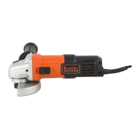
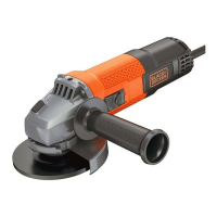
FEATURES (Fig. A)
1. Slider switch
2. Cable
3. Tool free guard
4. Body grip
5. Side handle (2 positions)
6. Spindle lock button
OPERATION
Operatingyour angle grinder
(Fig. A)
To switch on, push the slider switch forward
(1). To switch o, press the rear of the slider
switch.
Fitting the discs (Fig. B and C)
Proceed as follows:
• Disconnect the plug from the electricity
supply.
• Ensure the guard is fitted. Place the inner
flange (7) on the spindle. Ensure it is
located on the two flats.
• Place the abrasive disc on the spindle and
inner flange (8). Ensure it is correctly
located.
• Fit the threaded outer flange (9), making
sure it is facing in the correct direction for
the type of disc fitted. For grinding discs,
the flange (9) is fitted with the raised
portion facing towards the disc. For
cutting discs, the flange (9) is fitted with
the inner portion facing away from the
disc.
• Hold the spanner on the flats of the
spindle to prevent rotation of the disc
and tighten the outer flange with the
spanner provided.
• Press in the spindle lock button and
rotate the spindle until it locks (Fig. C).
Keeping the lock button pressed in,
tighten the outer flange with the spanner
provided.
Fitting sanding discs (Fig. D)
• Use a sanding disc with the backing pad
for sanding with your angle grinder.
• Disconnect the plug from the electricity
supply.
• Remove the guard.