26
INSTRUCTIONS FOR THE INSTALLER
ELECTRICAL CONNECTION
The appliance is supplied with a 15A power
RNWIſVVGFVQVJGUWRRN[EQTF%QPPGEVVJG
plug to a 15A General Purpose Outlet (GPO)
which is properly earthed and installed by an
authorised electrician. If a 15A GPO is not
available then an authorised electrician must
KPUVCNNVJGCRRNKCPEGCUHQNNQYU
FIXED WIRING.
The electrical connection must be carried
out in accordance with the current
standards and laws in force and by an
authorised electrician.
• Warning this appliance must be
earthed.
• Connection to the electricity supply must
be made by an authorised electrician to
a suitable isolating switch in accordance
with the requirements of SAA Wiring
Rules, AS/NZS 3000.
• A H05 RR-F 3x1.5 mm2 cable must be
used.
• Means of disconnection shall be provided
KPVJGſZGFYKTKPIKPCEEQTFCPEGYKVJVJG
Australian wiring rules.
• Remember that the earth wire must be
longer than the phase wires.
• Note: The power supply cable must be
positioned so that no part of cable can
come into contact with any surface which
could reach temperatures in excess of 75
K.
• If the supply cord is damaged, it must
be replaced by the manufacturer, its
UGTXKEGCIGPV QTUKOKNCTN[ SWCNKſGF
persons in order to avoid a hazard.
ADJUSTMENTS
• Always disconnect the appliance from
the electricity supply before making any
adjustment.
• All seals must be replaced by the technician
following any adjustment or regulation.
• The adjustment of the reduce rate (simmer)
must be undertaken only with burners
functioning on natural gas while in the case
of burners functioning on Propane, the screw
must be locked down fully (in clockwise
direction).
• “Primary air adjustment” on hob gas burners
is unnecessary.
• If the appliance cannot be adjusted to perform
correctly refer to the authorised service
provider in your area.
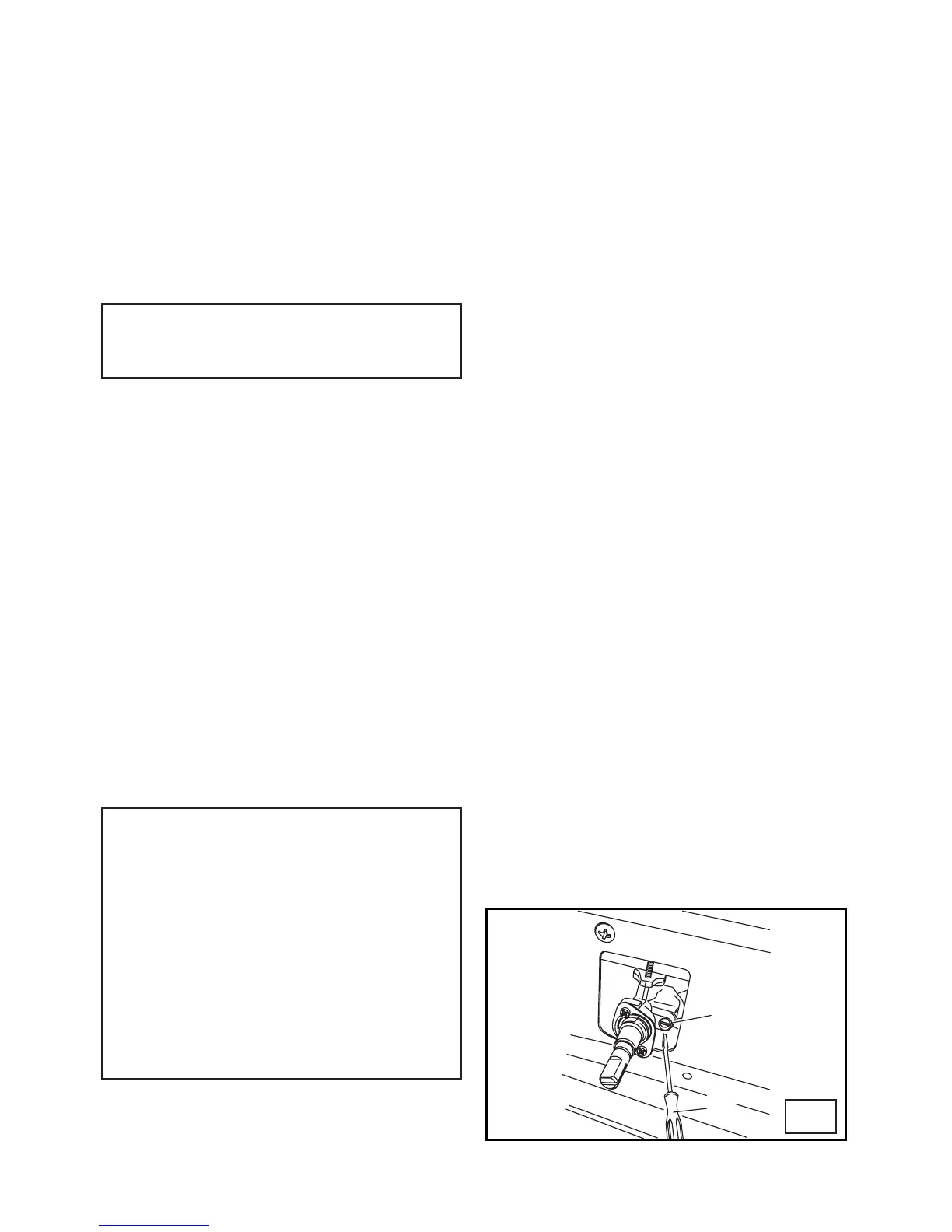
6#25ſI
All gas taps are male cone type with only
one way of passage. The adjustment screw
(V) is on the side of the stem.
Adjustment of the “Reduced rate” position
CUHQNNQYU
l• Turn the burner on and place the knob on
VJGő4GFWEGFTCVGŒRQUKVKQPUOCNNƀCOG
• Remove the knob of the tap which is
attached by simply applying pressure to
the rod.
• With a small screwdriver (C) turn to the
right or left the adjustment screw (V) until
VJGƀCOGQHVJGDWTPGTKUEQPXGPKGPVN[
regulated to the Low position.
Ŗ%JGEMVJCVVJGƀCOGFQGUPQVIQQWVYJGP
the knob is sharply switched from the “Full
on” to “Reduced rate” positions.
Hot Plate Ignition Failure
• Check alignment of burner holes to
electrode.
• Check aeration sleeve for adjustment for
gas type, location and ambient conditions.
• No spark, check ignition box failure or
power supply.
Before Leaving
• Check all connections for gas leaks with
soap and water. DO NOT use a naked
ƀCOGHQTFGVGEVKPINGCMU+IPKVGCNNDWTPGTU
to ensure correct operation of gas valves,
burners and ignition.
Ŗ6WTPICUVCRUVQNQYƀCOGRQUKVKQPCPF
QDUGTXG UVCDKNKV[ QHVJG ƀCOG 9JGP
UCVKUſGFYKVJVJGEQQMGTRNGCUGKPUVTWEV
the user on the correct method of
operation.
• In case the appliance fails to operate
correctly after all checks have been
carried out, refer to the authorised service
provider in your area.
 Loading...