Voltage supply
-
We
recommend a
minimum
cross section
of
2.5
mm
2
•
-
Route commercially available
plus
cables
to
the battery
and connect via fuse holder.
-
Use
cable glands for holes
with
sharp edges.
-
Securely fasten
commercially
available minus cables
to
a
noise-free earth
point
(chassis screw, chassis metal) (not
to
the minus pole
of
the
battery).
- Scrap
the
contact surfaces
of
the earth
point
until they
are
bright
and grease
with
graphite grease.
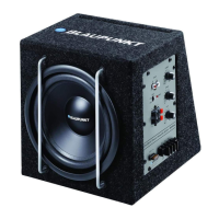
Connection
(
J1
)
is
connected
to
the
positive pole
of
the
battery and connection
(
i~
':
,
to
negative
vehicle
ground. The
control
ofthe
XLf200
A should ideally
be a two-channel con-
trol, either via
the
preamplifier outputs or the loudspeaker
outputs
of
the car sound system. A control
solely
via
the right
or left channel
is
also possible since the low-frequency por-
tion
of
the
music
is
generally identical on
both
channels.
Integrated
fuse
The fuse integrated
in
the
amplifier protects the
output
stage
and the entire electrical system in
case
of
a malfunction.
If
a
replacement fuse
is
used, never bridge fuses or replace
them
with
a
type
with
higher current.
Audio inputs
You
can select between 2 different audio inputs;
-
Cinch
(RCA)
-
Hi
level (loudspeaker connections)
Use
only one
of
the
audio inputs; otherwise,
it
may lead
to
audio interferences.
The
preamplifier outputs
are
connected
to
the cinch
(RCA)
sockets
(
~
)
of
the subwoofer box
via
a shielded sound cable.
With control
via
the loudspeaker outputs,
the
input
connec-
tions
of
pos.
(
~J
C
~
_
:
are fed
to
the
closest loudspeaker cables
(front or rear) on the
left and right. They are separated and
connected
to
the
input
connections. The polarity
of
the
+or-
connections must be observed. Bridge
output
stages
(BTL)
can also be connected directly
without
an
additional
adapter.
Switching on/off
A special feature
of
the XLf
200
A
is
its automatic switch-on:
The subwoofer box automatically
switches on
if
a music
signal
is
received.lf no music signal
is
received for more than
60
seconds,
the
Xlf
200
A
automatically
switches off.
VOL control
The
VOL
control
(
~
)
is
used
to
adjust the
input
sensitivity
of
the power amplifier
to
the
output
voltage
of
your car sound
system preamplifier
output.
The adjustment range
is
from
0.1
V
to
7.5
V.
If
a car sound system
of
a third party manufacturer
is
con-
nected, the
input
sensitivity must be adjusted corresponding
to
the manufacturer data.
XLf200A
A few important explanations
in
this context:
By
turning
the
control
clockwise, the
input
sensitivity
of
the
amplifier
and, therefore,
also
the volume increases. However,
this
is
not
a
volume
control; no
further
amplifier
output
can
be achieved in the end position, even
if it
may sound
like
that
at the beginning. The system
merely
increases
the
volume faster
if
the volume control
of
the
car
sound system
is
turned up.
CROSSOVER
frequency
control
The
CROSSOVER
control
C
~
)
allows
setting
the
desired entry
frequency.
Example:
At a setting
of
150
Hz,
the amplifier
has
a frequency range
of
20
Hz
to
150
Hz.
Settings
The
following
control
setting
is
recommended
as
basic
setting before
putting
the device
into
operation: Sensitiv-
ity
(VOL)
Pos.
(
~
)
to
minimum,
PHASE
Pas.
(
~
)
to
0°,
filter
(CROSSOVER)
Pos.
(
~
)
to
approx.
80Hz. Switch
on
the
device
and select a musical piece
with
distinctive
bass
playback.
Increase
the
volume
of
your
car
sound system
to
the
desired
volume
level.
Now
slowly
increase
the
VOL
control
(
~)
until
you
can
hear a clear amplification
of
the
bass
level.
Next,
use
the
CROSSOVER
control
(
~
·
to
select a filter setting
that
provides a well-contoured
bass.
You
may have
to
alternately
optimise
the
sensitivity
setting
(
~
)
and the
filter
setting
(
5).
A droning
bass
with
excessive volume requires a
filter
setting
with
a
low
frequency.
The phase switch
(
~)
must be set
so
that
the
bass
is
inte-
grated
into
the
acoustic pattern
as
best
as
possible and
not
recognisable
as
an
individual source.
Also
check your settings
of
the
Xlf
200
A
with
the
bass
con-
trol
fully
open and,
if
necessary,
with
activated loudness. An
overloading
of
the
subwoofer box by selecting
an
excessive
amplification
(pas.
(
~))
results
in
a distorted playback and can
damage
the
loudspeaker.
Power-on indicator
(PRT
/PWR)
Green
LED:
Output
stage on, regular operating status.
Red
LED:
Output
stage
is
electronically switched
off
due
to
an error.
Recycling and disposal
~
Please
use
the
return and
collection
systems avail-
~
able
to
dispose
of
the product.
-
Subject
to
changes!
5

 Loading...