Do you have a question about the Blaupunkt Bremen and is the answer not in the manual?
Illustrates the signal generator connections for alignment procedures.
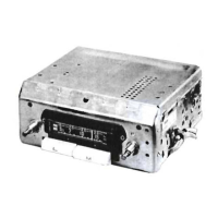
Diagram identifying key components on the radio's power chassis.
Details on electrolytic and fixed capacitors, including part numbers and ratings.
Locates and labels components as viewed from the top of the radio chassis.
Locates and labels components as viewed from the bottom of the radio chassis.
Specifies resistance and voltage values at various test points for troubleshooting.
Focuses on the vibrator unit and power supply section of the circuit schematic.
Lists part numbers and specifications for resistors, fuses, and miscellaneous items.
Details transformers, cabinet parts, and hook-up wire specifications.
This document provides a comprehensive guide for the Blaupunkt Model "Bremen" automobile receiver, a battery-operated unit designed for both broadcast (BC) and long wave (LW) reception. It covers alignment procedures, a detailed parts list, and schematic diagrams to facilitate maintenance and repair.
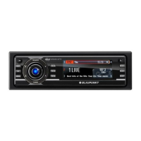
The Blaupunkt Model "Bremen" is an automobile receiver designed to provide radio entertainment in a vehicle. It operates on either a 6-volt or 12-volt storage battery, making it adaptable to different car electrical systems. The receiver is capable of tuning into two distinct frequency bands: Broadcast (BC) from 520-1650 KC and Long Wave (LW) from 140-300 KC. This dual-band capability allows users to access a wider range of radio stations, including standard AM broadcasts and specialized long wave transmissions, which were common for navigation or specific regional broadcasts during the period this device was manufactured. The receiver incorporates a mixer-oscillator (V1 ECH81/6AJ8), an IF amplifier (V2 EF89/6DA6), a detector-AVC-AF amplifier (V3 EBC91/6AV6), and an output stage (V4 EL84/6BQ5) to process the radio signals and deliver audio output. The vibrator (M1) is an essential component for converting the DC battery voltage into AC for the tube circuitry, a common practice in early car radios.
Operating the Blaupunkt "Bremen" is straightforward, with controls designed for ease of use in a vehicle environment. The primary controls include a volume control, which also incorporates a power switch, and a tone control for adjusting audio characteristics. The tuning mechanism allows users to select desired stations within the BC and LW bands. The alignment instructions emphasize setting the volume control to maximum during alignment, which is a standard procedure to ensure accurate calibration. The radio's design, with its robust chassis and components, indicates its suitability for the demanding conditions of automotive use. The inclusion of a dummy antenna and specific signal generator coupling points (e.g., to Pin 2 of ECH81(V1)) are features primarily for service technicians, ensuring precise alignment and optimal performance. The ability to tune in a weak station near 1400KC with the antenna fully extended, as mentioned in the alignment steps, suggests a practical method for fine-tuning the receiver in a real-world scenario after initial bench alignment. The push-button controls for band selection (Long Wave and Medium Wave, available in Ivory and Brown) offer quick and convenient switching between frequency ranges.
The manual provides extensive information to support the maintenance and repair of the Blaupunkt "Bremen" receiver. A detailed "Alignment Instructions" section outlines the precise steps for calibrating the receiver's various stages, including IF and RF alignment for both BC and LW bands. It specifies the use of a signal generator and an output meter, along with recommended alignment tools (Al-A11), which are cross-referenced with general cement and Walsco part numbers, making it easier for technicians to acquire the correct tools. The instructions also highlight critical settings like maximum volume and specific signal generator coupling points.
The "Parts List and Descriptions" is a crucial maintenance feature, categorizing components into Tubes, Electrolytic Capacitors, Fixed Capacitors, Coils (RF-IF), Controls, Vibrator, Selenium Rectifier, Fuses, Miscellaneous, Transformers (Power and Audio Output), and Cabinets & Cabinet Parts. Each entry includes the Blaupunkt part number, along with multiple replacement data options from various manufacturers (e.g., Aerovox, Centralab, Cornell-Dubilier, Mallory, Sprague for capacitors; Meissner, Merit, Miller, Ram for coils; Littelfuse, Buss for fuses). This extensive cross-referencing is invaluable for sourcing replacement parts, especially for older equipment where original parts may be scarce. Notes are often included to indicate specific conditions, such as "Not normally in distributors stock. Available thru distributor on order to manufacturer" or "Some versions may use 90mmf in this application."
The schematic diagram provides a visual representation of the circuit, aiding in troubleshooting and understanding component interconnections. Resistance readings for various tube pins are provided, measured from the output of the vibrator, which helps in diagnosing circuit faults by comparing measured values against specified norms. Voltage measurements, taken with a vacuum tube voltmeter, are also included, with notes on conditions like battery voltage (6.3 volts) and volume control setting (maximum) during measurement. The manual explicitly states that "Nominal tolerance on component values makes possible a variation of 15% in voltage and resistance readings," which is important for technicians to consider when evaluating discrepancies. The wiring data section specifies recommended Belden hook-up wire types for general use, shielded applications, and bonding straps, ensuring proper electrical integrity during repairs. The "Chassis-Top View" and "Chassis-Bottom View" diagrams, with clearly labeled components, facilitate physical identification and location of parts within the receiver, making assembly and disassembly for repair more efficient.
| Category | Car Receiver |
|---|---|
| CD Player | Yes |
| Bluetooth | Yes |
| USB | Yes |
| AUX Input | Yes |
| Power Output | 4 x 50 Watts |
| Compatibility | Android |
| Remote Control | Yes |
| Display | High Definition LCD |