ART. 35/09175-00 PAGINA 3 DI 4
'RRU:LQGRZDQG6KXWWHU'HWHFWRUZLWK:LUH,QSXW'&6
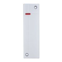
Parts Description:
/('LQGLFDWRU/HDUQ7HVW%XWWRQ
3UHVVWKHEXWWRQWRWUDQVPLWDOHDUQWHVWFRGHDQGHQWHU7HVWPRGH
for 3 minutes. The LED will light up whenever the Detector is
activated under Test mode.
0RXQWLQJ+ROHV&RYHUHGE\:KLWH&DSV
:LUH,QSXW7HUPLQLDO
Connect the terminal to any Normal Close (N.C) device
:LUH,QSXW7HUPLQLDO
Connect the terminal to Roller Shutter
-XPSHU6ZLWFKHV
For Jumper Switch functions, refer to later section “Jumper Switch
Setting”.
%DWWHU\,QVXODWRU
7DPSHU6ZLWFK
.QRFNRXWIRU([WHQVLRQ7HUPLQDOV
5LE0DUN
10. Magnet
Package Content
1 x Door Contact
[:DOOSOXJVDQGVFUHZV
1 x Adhesive pads
[9OLWKLXPEDWWHU\SUHLQVWDOOHG
Put the Control Panel into learning mode, then press the learn
EXWWRQWRWUDQVPLWOHDUQFRGH3OHDVHUHIHUWR&RQWURO3DQHOPDQXDO
to complete learn in process.
7KH 'HWHFWRU FDQ EH XVHG HLWKHU DV D GRRUZLQGRZ VHQVRU RU
transmitter for shutter or wired device, or all at the same time.
Choose the mounting location according to the Door Contact’s
usage.
$V D 'RRUZLQGRZ VHQVRU PRXQW WKH PDLQ ERG\ RQ WKH
door/window frame, and the magnet on the door/window.
0RXQWDVKLJKDVSRVVLEOH
$VDWUDQVPLWWHUIRUVKXWWHURUZLUHGGHYLFH mount close
to the device accordingly.
'RQRWPRXQWRQPHWDOOLFVXUIDFH
1. Remove the white caps covering the 2 mounting holes.
2. Drill holes into the mounting location using the holes as
template.
3. Screw the sensor onto the wall or door/window frame with the
screws and plugs provided.
$VD'RRU:LQGRZ6HQVRU
$OLJQ WKH PDJQHW ZLWK WKH 5LE 0DUN RQ PDLQ ERG\ VFUHZ
WKHPDJQHWRQWRWKHGRRUZLQGRZRUDSSO\ZLWKGRXEOHVLGH
DGKHVLYHWDSH7KH JDS EHWZHHQ WKH ERG\ DQG WKH PDJQHW
VKRXOGEHno more than 15 mm.
$VD7UDQVPLWWHU
5. Break through the knockout at top of the cover
)RU JHQHUDO ZLUHG GHYLFH connect the wire from device
WR :LUH ,QSXW 7HUPLQDO 0XOWLSOH ZLUHG GHYLFHV FDQ EH
connected to single Door Contact as long as the devices form
a closed loop with the Detector )LJXUH$
)RUUROOHUVKXWWHUFRQQHFWWKHZLUHIURPUROOHUVKXWWHUWR:LUH
Input Terminal 2. )LJXUH%
8. Replace the white caps.
Door/Window
Frame
Figure A Figure B
Learning
Installation
 Loading...