EasyManua.ls Logo

Blaupunkt MVP 01 - Page 8

Blaupunkt MVP 01
63 pages
Print Icon
To Next Page IconTo Next Page
To Previous Page IconTo Previous Page
Loading...
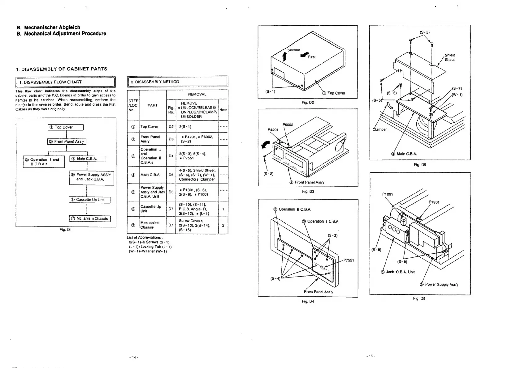
B.
Mechanischer
Abgleich
B.
Mechanical
Adjustment
Procedure
Second
Shieid
J
Sheet
1.
DISASSEMBLY
OF
CABINET
PARTS
1.
DISASSEMBLY
FLOW
CHART
2.
DISASSEMBLY
METIIOD
This
flow
chart
indicates
the
disassembly
steps
of
the
cabinet
parts
and
the
P.C.
Boards
in
order
to
gain
access
to
REMOVAL
item(s)
to
be
serviced.
When
reassembling,
perform
the
slep(s)
in
the
reverse
order.
Bend,
roule
and
dress
the
Fiat
REMOVE
Cables
as
they
were
originally.
%*
UNLOCK/RELEASE/
, .
UNPLUG/UNCLAMP/
UNSOLDER
@
Top
Cover
2(S-
1)
Clam
@
Top
Cover
@®
Front
Panel
Ass'y
@
Operation
|
and
®
Main
C.B.A
NC.B.A.s
*
P4201,
*
P6002,
(S-
2)
3(S-
3),
5(S-
4),
@
Main
C.B.A.
*
P7551
Fig.
DS
4(S-5),
Shield
Sheet,
(S-
6),
(S-7),
(W-
1),
Connectors,
Clamper
®
Power
Supply
ASS'Y
and
Jack
C.B.A.
*
P1301,
(S-
8),
2(S-8),
*
P1001
(S-
10),
(S-
11),
P.C.B.
Angle-
R,
3(S-
12),
*
(L-1)
@
Mchanism
Chassis
Screw
Covers,
2(S-
13),
2(S-
14),
{S-
15)
Mechanical
Chassis
Fig.
D1
List
of
Abbreviations
:
2(S-
1)=2
Screws
(S-
1)
(L-
1)=Locking
Tab
(L-
1)
(W-
1)=Washer
(W-
1)
G)
Jack
C.B.A.
Unit
©
Power
Supply
Ass'y
Front
Panel
Ass'y
Fig.
D4
Fig.
D6

Related product manuals