3
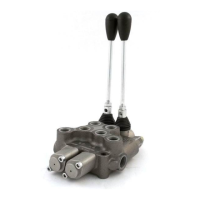
BM40/2 JOYSTICK MONOBLOCK DIRECTIONAL CONTROL VALVE / INSTRUCTIONS MANUAL
BM40 TECHNICAL SPECIFICATIONS
Work Flow / Max Flow 9 GPM / 12 GPM
Relief valve setting 2,100 PSI
Relief valve range 1,300 to 3,600 PSI
Inlet/Outlet Ports 10 ORB Side / 8 ORB Top
Work Ports 8 ORB
BM40 MAIN FEATURES
Zinc plating protects against corrosion and rust
Precise ow metering to accurately control actuator speed
Power beyond capability for easy addition of valves
downstream
Easy to convert from Open to Closed center
Customizable with a variety of spool and positioner options
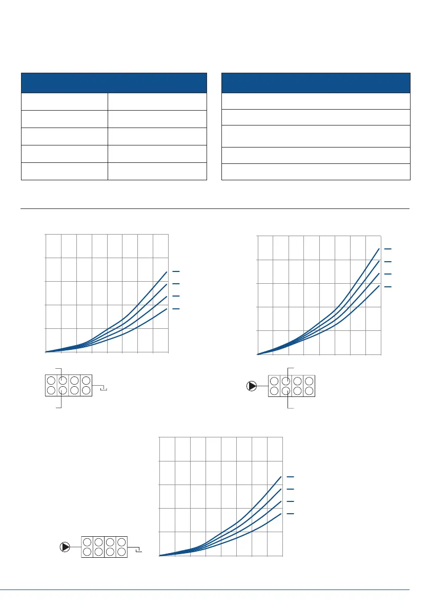
PRESSURE DROP
0
50
100
150
200
250
0 2 4 6 8 10 12 14 16
PRESSURE (psi)
FLOW (gpm)
/4
/3
/2
/1
BM40 A-T PRESSURE DROP
0
50
100
150
200
250
0 2 4 6 8 10 12 14 16
PRESSURE (psi)
/4
/3
/2
/1
BM40 P-A PRESSURE DROP
0
50
100
150
200
250
0 2 4 6 8 10 12 14 16
PRESSURE (psi)
FLOW (gpm)
/4
/3
/2
/1
BM40 P-T PRESSURE DROP
B
A
T
4 3 2 1
P
B
A
1 2 3 4
P
1 2 3 4
T