4
Installation of the earth (Drawing 1)
1 Pull the cable (B) through the strain relief (F) before tting the synthetic strain relief (F) onto the earth bolt (A). Position the strain relief
(F)atapproximately10cmfromtheeye(H) of the earth cable (B).
2 Place the eye (H) of the cable (B) onto the earth bolt (A) that is tted to the housing.
3 Then place a toothed lock washer (C), a hexagon nut (D) and another toothed lock washer (E) on top of the eye (H).
4 Fit the strain relief (F)ontop,creatingaloopofØ5cm.
5 Finally place the lock nut (G) onto the earth bolt (A).
6 Oncethevariousnutshavebeenplacedontotheearthbolt(A) in the correct sequence, they can be tightened with a spanner or a ring
spannernumber8.Donottightentoormly,otherwiseyoumaycrackthestrainrelief.(Thetransparentnutthatwasscrewedontheearth
bolt (A) on delivery has no further use, and can be discarded).
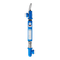
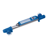
Installation of the device (Drawing 2)
The Blue Lagoon UV-C Timer must never be installed behind the Ph regulator or the salt electrolysis system in your swimming pool
installation. The ideal location to install your device is behind the pump and the lter. Never submerge this device in water. The installation
mustalwaystakeplaceoutsideofthepool.Ensurethatthereisalwayswaterowingthroughtheunitwhenthelampison.
1 Determinewherethedevicewillbeinstalled.Makesuretoleaveafreearea(+/-1metre)inordertobeabletoremovethelamp(K) /
quartzglass(M) for the purpose of replacement and/or maintenance.
2 Fit the supplied pipe clips (O) in xed positions, press the unit into the pipe clips and tighten the three-part coupling (I). Pay hereby
attention to the correct position of the sealing rings (P),bothwithregardtotheconnectionsandthequartzglass(see drawing 2).
3 Fit the unit into the circuit using the three-part couplings (I).Theinletandoutletofthethree-partcouplingisØ63mm.Ifyourpipesare
smallerthan63mm,youcanusetheadapter(Ø63xØ50mm)(T). This must be glued onto the three-part coupling (I). On one side of the
adapter (T), there is a screw thread on the inside giving the option of tting an adapter, with a sealing ring (not included in the delivery),
ontoitifnecessary.Adaptersetscanbeobtainedfromyourdistributor(articlenumberB290020).
4 Unscrew the screw ring (N) from the housing (U). Remove the UV-C lamp (K) from the supplied case (see packaging) and carefully slide the
lampintothequartzglass(M). Carefully connect the white lamp holder (L) to the UV-C lamp (K) and then screw the screw ring (N) hand-
tight onto the housing (U).
5 Activate the pump and check the ow and any leakage of the system.
6 PuttheplugoftheUV-Cdeviceinawallsocketwithasafetygroundandttedwitharesidualcurrentcircuit-breaker.Checkwhetherthe
lamp is operating by looking through the transparent components of the unit. The unit is switched o by pulling the plug out of the socket.
Instructions for use of the digital time meter
As soon as the Blue Lagoon UV-C Timer is switched on, the program will carry out a self-test. The display will automatically show the
following,oneaftertheother:8888(displaytest);randsoftwareversionnumber;50Hor60Hindicationofthemainsfrequency
Following this, the display will show the meter reading.
WhentheUVClampisswitchedonforthersttime,orafterthe“reset”functionhasbeenused,thevalue‘4500’willappearonthedisplay.A
dot next to the digit on the far right of the display will blink every second; this indicates that the counter is running.
Thedisplayisautomaticallysettothefactoryreadingof4,500hours.TheUV-Clampoperatesat100%radiationforupto4,500hours.After
4,500hours,theradiationwillweaken,andmaybecomeinsucienttoobtainthedesiredresults.
If the UV-C lamp had already been used previously, and is switched on again, the display will indicate the value it had at the time it was
switched o earlier. If you had increased or reduced the value of the time meter yourself, the display will indicate the latest counter reading it
had before it was switched o.
The settings of the time meter can be modied if you wish. This is carried out as follows:
After holding down the switch (R) underneath the display for 5 seconds, the display will show “rSt”, to indicate that the user menu has been
selected. Once the switch (R) has been released, the meter indication and “rSt” will blink alternately on the display. By briey pressing the
switch again, it is now possible to step through the menu options. There are 3 available setting options in the menu: “rSt” “UP” and “dn”.
 Loading...