AT2050 Air Hammer
3
Specifications
Blows per minute................................................ 3,400
Piston Stroke.........................................2.75” (70 mm)
Chuck and Bit Size........0.401" (10.2 mm) Shank only
Recommended Air Pressure.......................................
................................. 90 psig (6.2 bar, 620 kPa) max
Air Consumption, Working ............2.5 cfm (18 SCFM)
Air Inlet Thread Size................................1/4"–18 NPT
Air Supply Hose Size ...............................5/16" ID min
Air Supply Hose Length ...................... 30' (10 m) max
Length .................................................7.38” (187 mm)
Weight.................................................3.5 lbs. (1.6 kg)
*Sound Pressure Level .................................99.0 dBa
*Sound Power Level....................................111.0 dBa
**Vibration Level............................................. 3.0 m/s²
Specifications at 90 psig (6.2 bar, 620 kPa)
*Tested in accordance with ISO Standard 3744
and Pneurop test code PN8NTC1.
**Tested in accordance with ISO Standard 8662-2
Applications
AT2050 Air Hammer provides blows that is intended for
heavier duty applications, such as cutting large bolts
and rivets, separating ball joints, cutting heavy gauge
sheet metal, driving bushings, etc.
Air Supply
Air tools operate best on clean, moisture-free, well-
lubricated air at a constant pressure of 90 psig (6.2
bar, 620 kPa) maximum.
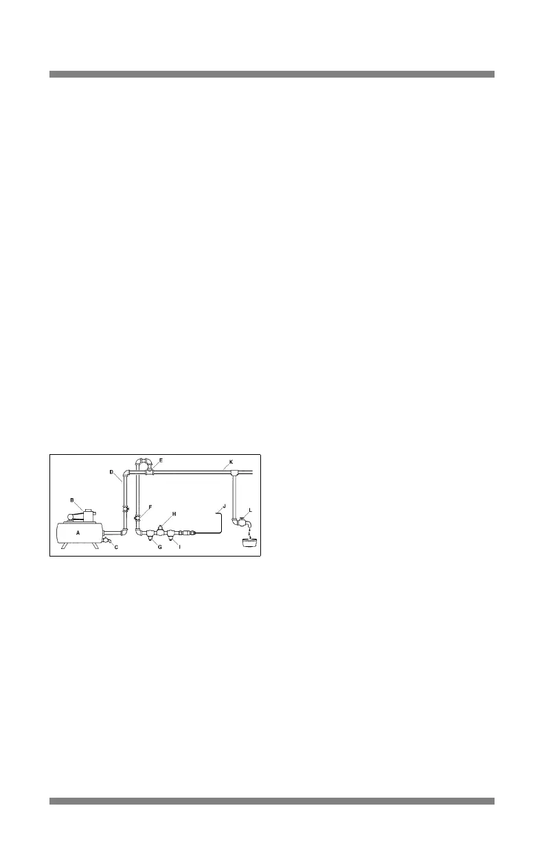
A – Receiver Tank, Minimum 40 Gallons
(151.5 liters)
B – Compressor, Sufficient Capacity
C–Drain, Daily
D – Pipe and Fittings, Minimum 1/2"
E–Top Air Intake
F – Shut Off Valve, Easily Reached
G – Filter
H – Air Regulator, Set at Working Pressure
I – Lubricator
J – Air Tool Connection
K – Low Spot, Water Trap
L–Drain, Daily
Piping System
The piping system should be large enough to avoid an
excessive pressure drop under maximum flow
conditions. All pipe fittings and hose outlets should be
1/2" and should be arranged so there are no low spots
that collect water which cannot be drained daily. Do not
use an air hose less than 5/16" inside diameter or one
that is too long because pressure drop under
maximum flow conditions could reduce performance.
Assessories are available for air tight connections. The
Snap-on AHC22B Quick Coupler and the AHC22MA
and AHC22FA adaptors are recommended for use with
this air tool.
Air Compressor
The air compressor should have sufficient capacity
to deliver 2.5 cfm (18 SCFM) at 90 psig (6.2 bar,
620 kPa) at each outlet while the tool is running. The
receiver tank should have sufficient capacity to provide
surge balance for each air tool.
Filter
The Snap-on AHR424 Filter, or equivalent, should be
used to assure clean air for the air hammer. Water, dirt
and scale act as abrasives which could damage the air
hammer. A filter unit should be installed between the
compressor and the air regulator and air lubricator.
Air Regulator
Regulated air pressure is necessary for proper
performance of the air hammer. The Snap-on AHR426
Regulator, or equivalent will adjust and maintain the
recommended air pressure of 90 psig (6.2 bar, 620
kPa). Pressure less than this reduces efficiency, while
pressure greater than this increases blows and speed
beyond the rated capacity—creating potential hazards
and possible damage to the air hammer. Check the air
pressure at the regulator while using the hammer in a
normal manner.
Air Line Lubricator
✓ Do not use a heavy grade of oil because stalling
and low performance will result.
The preferred method of lubricating the air hammer
motor is to use an air line lubricator such as the
Snap-on AHR428 Lubricator. It should be filled with
Snap-on IM6 Air Motor Oil or a good grade of
SAE 10W oil. If an air line lubricator is not used,
lubricate the air motor by injecting approximately
1/4 oz. (7 ml) of IM6 Air Motor Oil into the air inlet of
the hammer each day before using it. IM6 Oil is
specially formulated for air tools and no flushing
solvent is needed.
Flushing
If the unit seems sluggish apply 3 or 4 squirts of IM6
Air Motor Oil into the air inlet of the hammer each day
before using, and again at the end of each work day.
Figure 1: Air Supply
 Loading...