Marine Electrical Prod
ucts
Features
• Switches 2 - 120/240V AC Sources
• Compact solution when circuit protection is provided elsewhere
• Allows connecting one of two different AC sources to one circuit
• Heavy duty industrial rated switches
• Intuitive function―one handed operation
• UL listed switches
Specications
Amperage Rating: 65 amp maximum service
Voltage Rating: 600 Volts AC Maximum
Maximum Wire Size: 6 AWG
Minimum Wire Size: 12 AWG
Terminal Recommended Torque: 40 lb-in.
Inches Millimeters
Overall Dimensions: 2.520 x 2.520 64.00 x 64.00
Mounting Depth: 3.69 93.8
Maximum Panel Thickness: 0.157 4.00
BlueSeaSystemsInc. Phone(360)738-8230
425SequoiaDrive Fax(360)734-4195
Bellingham,WA98226USA www.bluesea.com
6671 Rev.002
WARNING
These instructions are intended to provide assistance with the
installation of this product, and are not a substitute for a more
comprehensive understanding of electrical systems. We strongly
recommend that a competent electrical professional perform the
installation of this product.
If either the switch front or back is to be exposed to water it must be
protected with a waterproof shield.
The switch must not be installed in explosive environments such as
gasoline engine rooms or battery compartments, as the switches
are not ignition proof.
The vessel’s shore power cord must be disconnected form shoreside
power before installing this electrical switch.
If an inverter is installed on the vessel its power leads must be
disconnected at the battery before the panel installation. Be aware that
many inverters have a “sleep mode” in which their voltage potential
may not be detectable with measuring equipment.
If an AC Generator is installed aboard it must be stopped and rendered
inoperable before the switch is installed.
Verify that no other AC or DC source is connected to the vessel’s
wiring before the switch is installed.
Guarantee:
Blue Sea Systems stands behind its products for as long as you own
them. Find detailed information at www.bluesea.com/about.
For customer service, call 800-222-7617.
Installation
1. DisconnectallACandDCpower
Disconnect all AC power originating on or off the vessel. This includes
inverters, generators, shore power attachments and any other device
capable of supplying AC power to the ship’s circuits.
Disconnect the main positive DC cable from all batteries to eliminate
the possibility of a short circuit and to disable the inverter while
installing the switch.
2. Selectmountinglocationandcutopening
Select a mounting location which is protected from water on the front
and back of the switch and is not in an area where ammable vapors
from propane, gasoline or lead acid batteries accumulate. AC rotary
switches are not ignition protected and may ignite such vapors.
Using the template provided, drill the mounting surface where the
switch is to be mounted. The mounting surface maximum thickness is
0.157” (4.00mm). Do not yet fasten the switch to the mounting surface.
3. Installsource1,source2andoutputwires
Install the feed wires from AC Shore Power and AC Generator. Install
the output wires. Refer to the wire sizing chart to select the minimum
wire size. Connect the black AC hot, white AC neutral and green AC
safety ground as shown in the illustration. To avoid excess wire
temperatures when cooling may be limited, we recommend using at
least 12 gauge wire for 30A and 8 gauge wire for 50A.
Do not confuse the neutral current carrying wires (sometimes called
ground) with the green normally non-current carrying wires (sometimes
called grounding). These two wires must be connected only at the
source of power, nowhere else.
A double pole circuit breaker must be installed within 10 feet of the
shore power inlet, ahead of this switch. The measurement is made
along the conductors.
The switch provides switching, but does not provide circuit protection.
It is not a substitute for a main circuit breaker.
Wiresizingchart
Use the wire sizing chart below to determine the proper branch and
feed circuit wire sizes.
AllowableAmperageofConductors
4. Testing
It is very important that the wiring be connected according to the
diagram. The line and neutral from each source must be paired
together and not connected such that the switch selects line from one
source and neutral from another. Verify the connections and see that
each connection is securely tightened, including the terminals for the
jumpers installed on the switch where no wires are attached.
It is possible to verify the connections using an ohmmeter before power
is applied. These procedures take a little time, but are recommended,
especially if some elements of a previous installation might not have
been properly labeled or followed the expected color codes.
Page 1 of 3
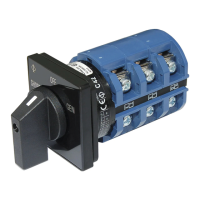
ACRotarySwitch
2Positions+OFF,3Pole
9019
Note: Thischartassumeswirewith105°Cinsulationrating
andnomorethan2conductorsarebundled.
Notsuitableforsizingexibleshorepowercords.