507787B02 Issue 2336 Page 9 of 22
Duct System and Filters
Duct System
The air handler is provided with anges for the connection
of the supply plenum.
Supply and return duct system must be adequately sized
to meet the system’s air requirements and static pressure
capabilities. The duct system should be insulated with
a minimum of 1” thick insulation with a vapor barrier in
conditioned areas or 2” minimum in unconditioned areas.
Supply plenum should be the same size as the anged
opening provided around the blower outlet and should
extend at least 3 ft. from the air handler before turning or
branching o plenum into duct runs. The plenum forms
an extension of the blower housing and minimizes air
expansion losses from the blower.
Filters
A lter is provided. Table 2 lists the lter size for each unit.
Model Filter Size – in.
-018, -024, -030 15" x 20" x 1"
-036, -042, -048, -060 18" x 20" x 1"
Table 2. Unit Air Filter Size Chart
If a high eciency lter is being installed as part of
this system to ensure better indoor air quality, the lter
must be properly sized. High eciency lters have a
higher static pressure drop than standard eciency
glass/foam lters. If the pressure drop is too great,
system capacity and performance may be reduced.
The pressure drop may also cause the limit to trip
more frequently during the winter and the indoor coil
to freeze in the summer, resulting in an increase in the
number of service calls. Before using any lter with this
system, check the specications provided by the lter
manufacturer against the data given in the appropriate
Product Specications.
IMPORTANT
Installing Duct System
Connect supply air duct to the ange on top of the air
handler. If an isolation connector is used, it must be
nonammable.
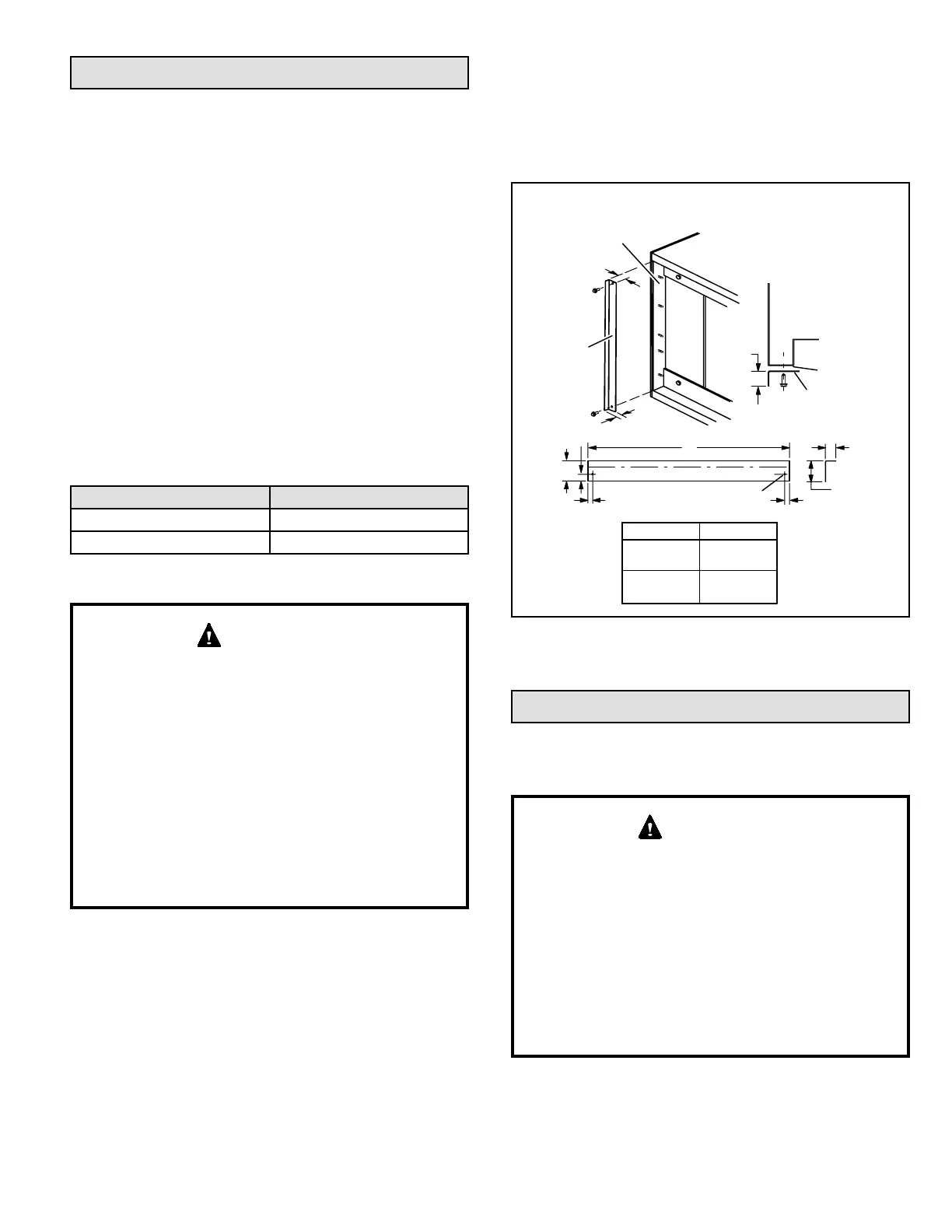
Field-Fabricated Return Air Duct Flange for
Horizontal Applications
A return air duct system is recommended, but not factory-
provided. If the unit is installed in a conned space or
closet, run a full-size return connection to a location outside
the closet.
BOTTOM OF
CABINET
DUCT
ADAPTER
1−1/2
(38)
”A”
BRAKE DOWN 90 DEGREES
1/4 (6) DIA.
2−HOLES
"A"
1−1/2(38)
3/4
(19)
3/4
(19)
1−1/2
(38)
3/4
(19)
1/2
(13)
3/4
(19)
DUCT
FLANGE
CABINET
DOOR FLANGE
UNIT SIZE
Cabinet and Duct Flange
-018, -024,
-030
-036, -042,
-048, -060
18-3/8"
21-1/2"
Figure 9. Cabinet and Duct Flange
Brazing Refrigerant Lines
Refrigerant lines must be connected by a qualied
technician in accordance with established procedures.
Refrigerant lines must be clean, dry, refrigerant-grade
copper lines. Air handler coils should be installed
only with specied line sizes for approved system
combinations.
Handle the refrigerant lines gently during the installation
process. Sharp bends or kinks in the lines will cause a
restriction.
Do not remove the caps from the lines or system
connection points until connections are ready to be
completed.
IMPORTANT