- 13 -
4.9 Remote Start Logic System
Blue 5c provides an ‘open collector’ continuous closure to ground for each input. Interfacing to these
contact points will vary depending upon the equipment to be remotely started. Contact LPB customer service
for tech hints and ideas. You may also find them on our www.blue5c.com website.
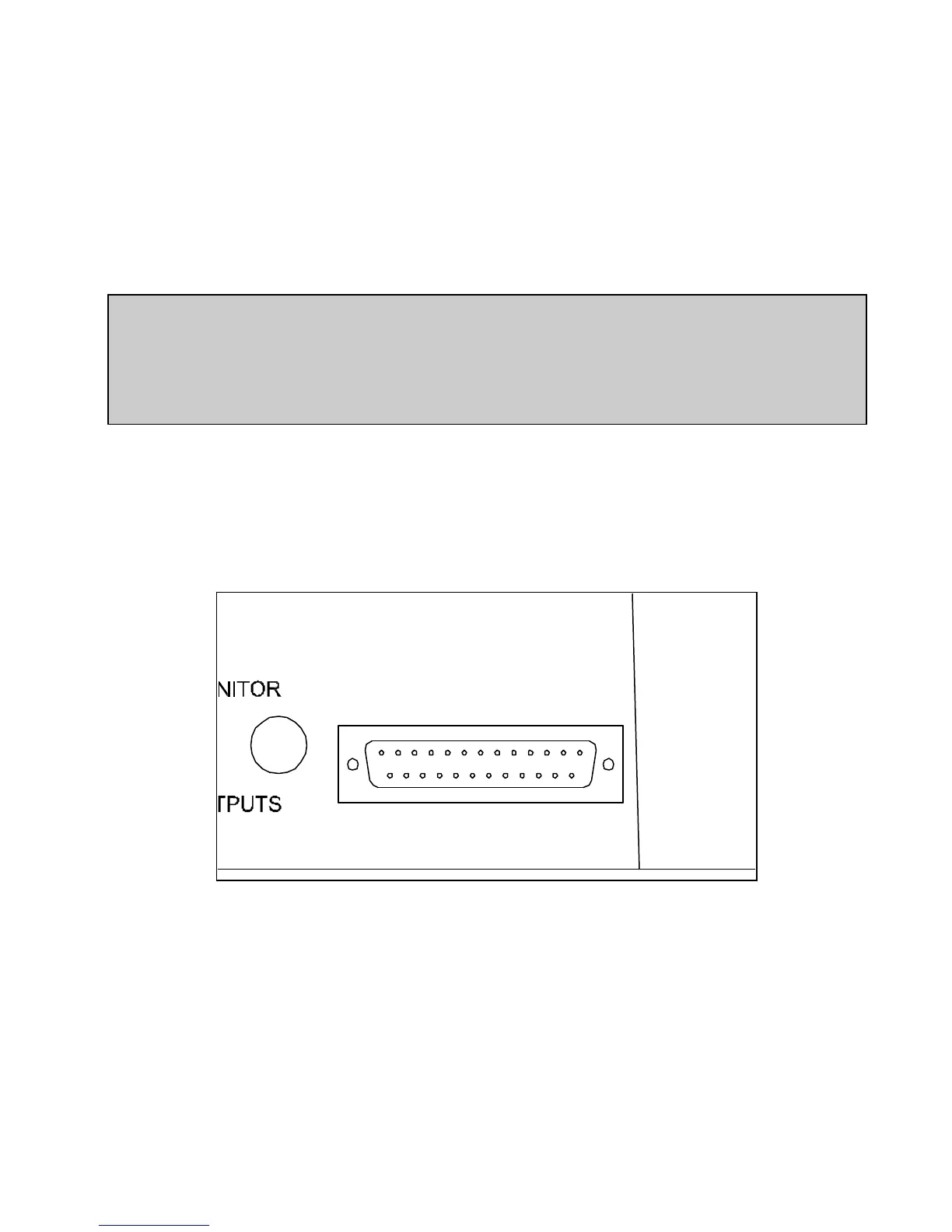
Located of the rear of the console is a 25 pin ‘D’ connector. A label on the back of this manual indicates the
function of each of these pins. Referring to figure 4.9, the 10 pins labeled ‘Tally 1’ thru ‘Tally 10’ are the
open collector that corresponds to the associated input. ‘Tally 1’ corresponds to Input 1, Tally 2 Input 2 and
so on. When the Input and the associated channel ‘ON’ button is active, the associated Tally pin will be at
ground potential until either the Input is un-selected or the Channel is turned ‘OFF’.
!! WARNING !!
Do Not connect 120vac directly to any pin on this connector. Severe damage
to the console will result and possible electric shock hazard. Switching of
large AC voltages should only be done thru external relays capable of
handling the voltage and current.
The remote start pins are as follows:
Tally 1 (Input 1) = pin 11 Tally 6 (Input 6) = pin 21
Tally 2 (Input 2) = pin 10 Tally 7 (Input 7) = pin 7
Tally 3 (Input 3) = pin 9 Tally 8 (Input 8) = pin 20
Tally 4 (Input 4) = pin 22 Tally 9 (Input 9) = pin 6
Tally 5 (Input 5) = pin 8 Tally 10 (Input 10) = pin 19
AUX & LOGIC OUTPUTS
R
1 13
14 25
Fig. 4.9
4.9.1 On Air Light
A unique feature of The Blue 5c is the built in “ON AIR” indicator. It will come on whenever the monitors
are muted. Setting and muting the monitors is explained in section 4.8 In addition, an ‘ON AIR’ tally appears
on pin 3 of the 25 pin “D” connector located on the rear of the unit. Like the other tally pins, this is an ‘open
collector’ which, when active, will be at ground potential and continuous until the channel is turned off.
This tally is typically used to drive a low-voltage DC activated solid state relay. The positive (+) pin of the
relay coil should be connected to +5VDC (located on pin 18 of the 25 pin “D” connector). The negative (-)
pin of the relay coil is connected to the ON AIR TALLY (pin 3). This approach will allow the relay to
become active when the selected input and corresponding channel are on (mute activated: see section 4.8). A
120 VAC On-Air light is connected to the relay contacts thus isloating the AC from the internal components
 Loading...