- 8 -
4.3.1 Grounding the Console
ON
CUE
OUT
PGM
OUT 1
2
3
4
5
6
7
8
9
10
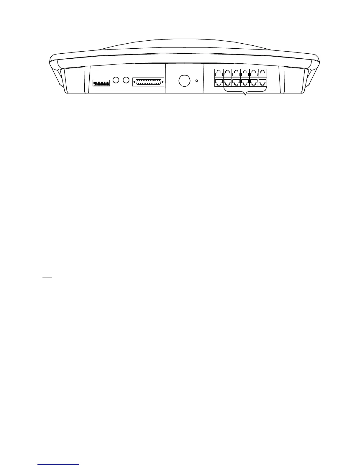
Ground
Power
Supply
MONITOR
AUX & LOGIC OUTPUTS
MUTING
L R
OUTPUTS
1 13
14 25
A grounding lug is provided on the rear of the console.
Connect the console grounding wire to the central grounding point for the studio. Do not count on metal
cold water pipes as a console grounding point, as the use of plastic pipe and fittings or Teflon tape elsewhere
in the line may place the pipe above ground potential. Also, condensation on cold water pipes can corrode
ground connections.
It is also best to avoid the facility AC power ground as a grounding point, especially in old construction.
While adequate for safety purposes, it may have a small voltage potential, and serve as a source for electrical
noise in the system. In new construction, early consultation with the electrical contractor can result in an AC
grounding system that is adequate for audio purposes.
One final tip: Remember that metal equipment racks also provide a grounding path for any equipment
mounted in them. This can be useful, as all equipment in a rack can be grounded via a single bus wire.
However, it is easy to presume that a piece of rack mounted equipment is grounded only by its AC connector,
when in fact it sees a second path to ground through the rack itself, thus creating a hidden ground loop.
4.4 Connecting the Power Cord
We highly recommend the use of an external surge suppresser to reduce the possibility of damage caused by
lightning and other transients on the AC power line.
Insert the power supply plug into the rear of the console labeled POWER. Plug In the AC power cord. The
ON switches located on the console should be illuminated when pressed. DO NOT PROCEED IF THESE
LAMPS FAIL TO ILLUMINATE. If you find this condition, check for AC at the wall outlet feeding the
power supply. If this step does not restore normal operation then proceed no further. Call the LPB Customer
Service department immediately.
Upon verification that power is available to the console, installation of the audio input, output and logic
circuits can begin.
4.5 Audio Input Wiring
Tools required for installation include a soldering iron, RJ45 crimp tool and a small-gauge wire
stripper/cutter. A heat gun is recommended so that the ends of all jacketed cables can be served with heat-
shrink tubing.
The console wiring diagram should be drawn out ahead of time, for fastest installation, with all wires and
connectors clearly designated. Professional installation practices recommend that wires, cables and
connectors be numbered or labeled at the time of installation to match the wiring diagram. Wire ties, cable
brackets and other accessories also should be on hand prior to installation.
All audio inputs to the console are located at the rear of the console on an RJ45 connector.
Note that the nominal input audio input level for this console is 0 dbm. This level is typical of professional
audio equipment, however, consumer equipment often provides between –10 and –15 dbm of audio.
 Loading...