Do you have a question about the Bluesound Node 2i and is the answer not in the manual?
Instructions for removing the rear cover and lifting the upper housing section.
Steps for disconnecting internal cables and removing necessary screws.
Guidance on inserting the new interface and connecting motherboard components.
Steps for closing the housing, reinserting screws, and final checks.
Details on power supply requirements, module specifications, and fuse replacement.
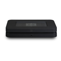
This document outlines the assembly instructions for a PCB interface designed for the Bluesound Node 2/2i, along with additional information regarding its operation and maintenance. The primary function of this PCB interface is to enhance or modify the existing functionalities of the Bluesound Node 2/2i device. The installation process involves several steps, starting with the careful disassembly of the Bluesound Node 2/2i unit, followed by the integration of the new PCB interface, and finally, the reassembly of the device.
The initial steps of the installation focus on gaining access to the internal components of the Bluesound Node 2/2i. Users are instructed to remove the rear cover by gently pulling it at the indicated points. This action reveals the internal structure and the screws that secure the top part of the housing. Two specific screws need to be removed to proceed. Once these screws are out, the upper part of the housing can be lifted. It's crucial to perform this step by tilting the housing only from the back of the device. Users should listen for distinct "clicks" as the housing is lifted upwards. Throughout this process, extreme care must be taken to avoid breaking any internal tapes or cables, which are delicate and essential for the device's operation. After successfully lifting the upper case, it should be carefully placed next to the main unit. The instructions explicitly state not to disconnect any cables at this stage, as the sockets are secured with adhesive, and unnecessary disconnection could lead to damage or complications.
The next phase involves disconnecting existing internal components to make way for the new PCB interface. Users are advised to disconnect both the small and large sockets. For this task, using longer pliers is recommended to ensure a secure grip and prevent damage to the surrounding components or the sockets themselves. Following this, several screws indicated by arrows need to be removed. These screws typically secure various internal plates or modules. Additionally, screws located on the back panel of the device must also be removed. These screws often hold the power supply unit and other external connectors in place.
Once the factory power supply and stiffening plate have been removed, users should identify a retaining pin. The new interface is then inserted into the module, ensuring that the indicated pin aligns and goes into the retaining hole. This step is critical for proper alignment and secure fitting of the new interface. After the new module is in place, it needs to be screwed on. The stiffening plate, which was previously removed, should also be reinstalled as depicted in the provided image. This plate helps to secure the module and maintain the structural integrity of the device.
A crucial connection involves the large JST connector. Users must connect this connector to the corresponding socket on the motherboard. When making this connection, it is important to twist the cable harness slightly. This action helps to ensure a proper fit and prevents strain on the cables. However, caution is advised to avoid pulling the cables out of the plug, as this could damage the connector or the wiring. Finally, the back panel is re-mounted by screwing the black screw into the indicated hole, securing the panel in place.
The reassembly process continues with closing the housing. This is done by first hooking the indicated latches. If the latches do not engage easily, a small amount of force may be applied, but users should be careful not to over-force it to prevent damage. After the housing is closed, the black screws that were previously removed are screwed back into their respective places, further securing the device's casing. The final step in the reassembly is to install the rear panel cover, which completes the external appearance of the device.
Upon completion of the installation, users should verify that only the factory power supply and two silver screws remain as leftover components. If there are any discrepancies in the remaining components, it is recommended to double-check the assembly process to ensure everything has been correctly installed and no parts are missing or incorrectly placed. This check helps to confirm the correct assembly and functionality of the device with the new PCB interface.
The document also provides additional information regarding the measurement and regulation aspects of the module. The power supply required for the module should be within a specific voltage range, between 5 and 5.1V. The module incorporates voltage measuring points, labeled VCC and GND, which are designed to measure voltage under load. These points are particularly useful for fine-tuning the power supply, especially if the power supply unit has the capability for such adjustments. The socket polarization is also indicated, showing the positive and negative terminals.
Regarding maintenance, the document highlights a specific component, "U2," which is a fuse. This fuse is an integral part of the security features of the device and is a replaceable part. A spare fuse is typically attached to the manual for convenience. The blowing of this fuse is a deliberate protective mechanism designed to safeguard the device from damage. It may activate due to an incorrect power supply voltage or an improper connection. It is important to note that the replacement of a blown fuse is not covered by the warranty, as it is considered a protective measure against user-induced issues. If a replacement is necessary, specific parameters for the fuse are provided: it should be a fast-acting fuse with an SMD-1206 housing, a voltage rating of 32V (maximum allowed 63V), a fuse current of 3A, a maximum allowed resistance of 30 mOhm (0.03 Ohm), and a maximum allowed voltage drop of 90 mV (0.09 V) at a 3A current. These detailed specifications ensure that the correct replacement fuse is used to maintain the device's safety and functionality.
| Supported Audio Formats | MP3, AAC, WMA, OGG, WMA-L, ALAC, OPUS, MQA, FLAC, WAV, AIFF |
|---|---|
| DAC | 32-bit/192kHz |
| Ethernet | Gigabit Ethernet RJ45 |
| Trigger | 12V Trigger Output |
| IR Input | Yes |
| Sample Rates | Up to 192 kHz |
| Bit Depth | 16-24 bit |
| Audio Outputs | Analog RCA, Optical, Coaxial |
| Wireless Connectivity | Wi-Fi (802.11 a/b/g/n/ac), Bluetooth |
| Dimensions | 220 x 46 x 146 mm |
| Weight | 1.12 kg |
| Processor | ARM Cortex A9 |
| Analog Audio Output | Stereo RCA |
| Digital Audio Output | Coaxial, Optical |
| USB | Type A (for external drive connection) |
| Streaming Services | Tidal, Qobuz, Deezer, Spotify, Amazon Music, Napster, HighResAudio, Murfie, KKBox, Bugs |
| Multi-Room | BluOS |
| Power Supply | Universal 100-240V AC |