01
02
P-07
03
Model B Installation
Open the door and put something in the doorway to ensure the door doesn't close throughout
installation.
Check the condition of the existing latch, ensure that it retracts fully when the handle is fully
pushed down. If it doesn't, you may need to replace the latch before fitting the Breeze handle.
Remove the existing handles. For handles with exposed screws, remove the fixing screws. For
rectangular backplate handles with hidden screws, carefully take off the outer cover plate to reveal
the fixing screws. For circular backplate handles with hidden screws, you may need to twist the
outer cover to remove it and reveal the screws. If the handle doesn't easily remove, check there is
no grub screw in the back of the handle grip. If there is, remove the grub screw, then remove the
handles and spindle.
Locate the hollow Breeze spindle (G) and the paper fitting template. Follow the instructions on the
template to ensure it lines up correctly. You can then use the template to mark the door with a
pen/pencil where holes need to be drilled. Do this on both sides of the door.
You will need a 10mm drill bit. Take your drill, make sure it is level and drill a hole through the door
at the marked positions. Check the other side of the door, if it was level, you won't see the marks
you made for holes.
You can check this was done correctly by putting the template back over the latch. The drilled
holes should match the template. If they don't, your drill may not have been level. Use your drill to
make these holes level.
If you haven’t already, please make sure the handles open in the correct direction. If they don’t, go
back and follow the ‘Change the handle direction’ instructions to make sure they open correctly
before moving to the next step.
With the external handle (A) in hand, take the connection bosses (H) and screw them into the
positions at the top and bottom of the inside face.
Take the spindle (G) and feed the wire through the hollow opening, then push the spindle into the
handle.
05
06
a
07
08
04
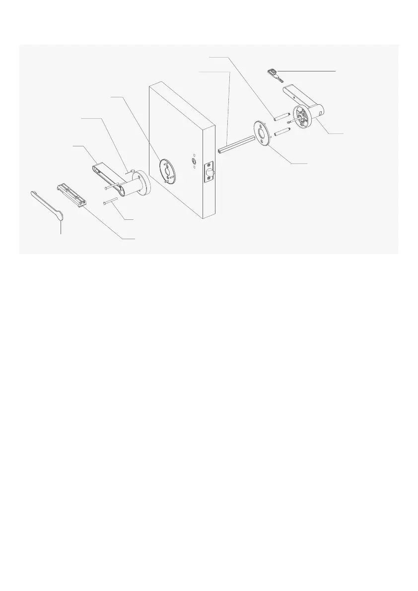
A External handle
E Handle mounting plate
E Handle mounting plate
F Key
G Hollow spindle
I Split bolt
K Setting needle
B-1 Internal handle cover B-2 Battery cassette
H Connection boss
B Internal handle
 Loading...