EasyManua.ls Logo

BMP Dynamicroll Frigo 2 - Page 14

BMP Dynamicroll Frigo 2
39 pages
Print Icon
To Next Page IconTo Next Page
To Previous Page IconTo Previous Page
Loading...
BMP EUROPE Srl
Rev. 6
Installation and user manual Dynamicroll® Frigo 2
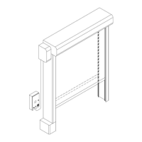
Electrical connections [ENCODER + PHOTOCELLS (SPIDER CABLE)]
C
Control panel
M
Three-phase motor
S
Signals distributor connection Spider
B
Electro-brake
E
Encoder
J
Curtain top sensor
R
Infrared photocell receiver
T
Infrared photocell transmitter
H
Wireless safety edge transmitter
W
Heating system
Wiring
Sections
1
Motor and brake supply cable
4G x 1,5 mm
2
+ 2 x 0,5 mm
2
2
Control panel / Mobile connector cable
7 x 0,5 mm
2
3
Mobile connector / Distribution connection Spider
7 x 0,34 mm
2
4
Encoder cable
4 x 0,34 mm
2
5
Curtain top sensor cable
3 x 0,34 mm
2
6
Photocell receiver cable
3 x 0,34 mm
2
7
Photocell transmitter cable
3 x 0,34 mm
2
8
Hot blower cable
2 x 2,5 mm
2
9
Heating cables transformer cable
2 x 2,5 mm
2
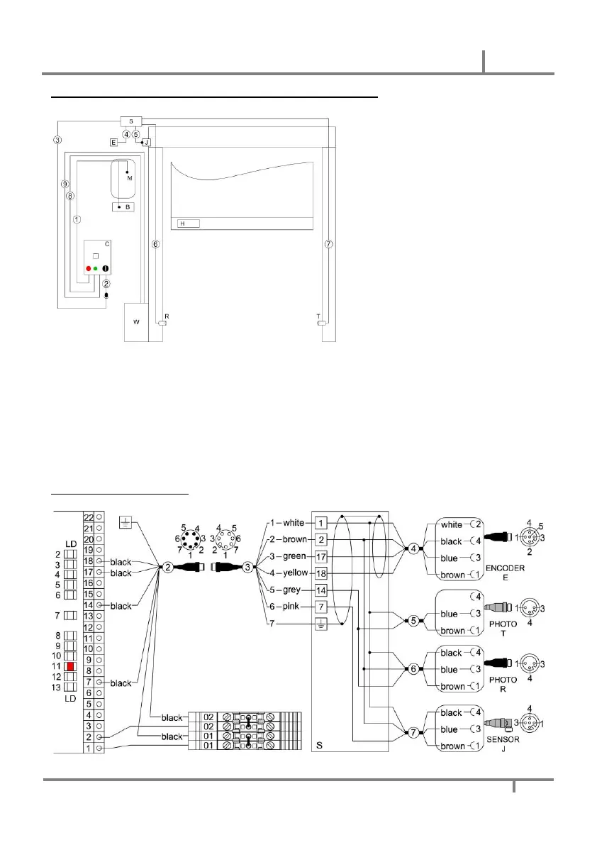
Spider cable connections detail