Installation and user manual – Dynamicroll® Frigo 2
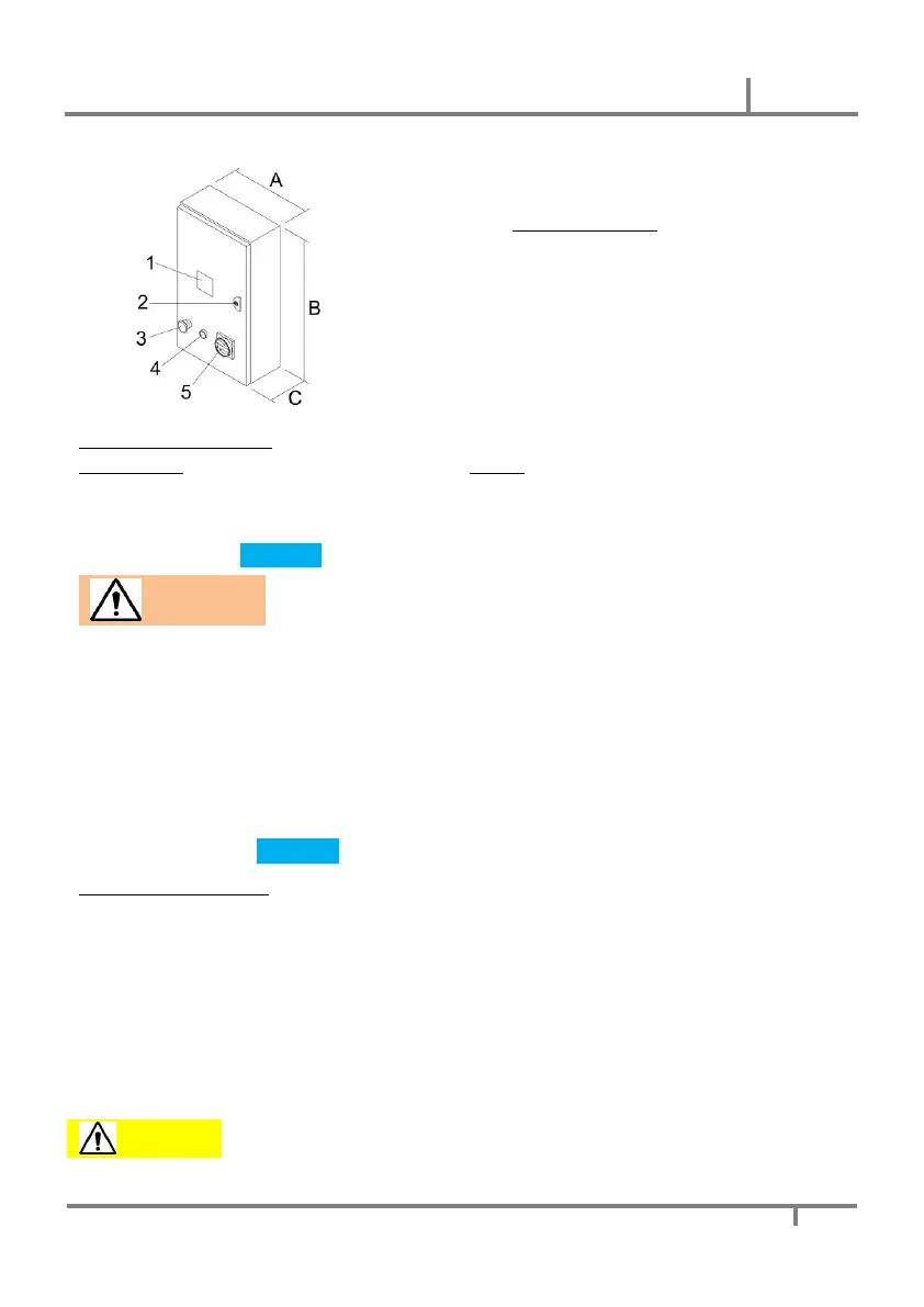
CONTROL PANEL
3 - EMERGENCY STOP button
4 - Opening/closing button (START)
Safety devices and guards
Safety devices:
- Photocells
- Curtain top sensor
- Wireless safety edge
Guards:
- Top heading cover
- Columns cover
- Motor cover
Standard safety devices depend on size of the door
DO NOT REMOVE FIXED GUARDS.
The manufacturer assumes no responsibility for the use of the machine without
fixed protections. Immediately restore the protections that are damaged or worn.
9. INTENDED USES AND USAGES LIMITS
The automation is an industrial door with vertical movement designed to close internal or external
compartments, which allow the passage between two rooms. The passage is generally intended for logistic,
such as for example trucks, forklifts, AGVs etc., or of people. The mixed passage through the door is allowed
only if it is safe; In this case a risk analysis by the user is necessary to make the passage safe. The door must
be used for the purpose for which it was designed. Any other use is to be considered improper and therefore
dangerous. The manufacturer declines all responsibility for damage resulting from improper, incorrect or
unreasonable use. The use of the door as an emergency exit is not foreseen, since it is not homologated.
10. INSTALLATION
Installation must be done by trained technician
General safety instruction
For the mechanical installation, suitable means must be used for lifting the automation and for accessing the
parts at height. Check that the structure on which the door is installed is suitable to support the weight of the
machine, also taking into account dynamic and static phenomena.
Electrical connections and adjustments must be made respecting what is indicated in this document and
respecting Good Technique. Before connecting the power supply, make sure that the plate data correspond to
that of the electricity distribution network.
Provide a suitably sized switch / disconnector on the power supply.
Check that the power supply line is protected by a differential device and by overcurrent protection. Connect the
door to an effective earthing system.
At the end of the installation, the installer must provide all information relating to the automatic, manual and
emergency operation of the door and give the user of the system the use and maintenance manual.
A WRONG INSTALLATION CAN BE A SOURCE OF DANGER DURING THE
OPERATION OF THE MACHINE
 Loading...