11
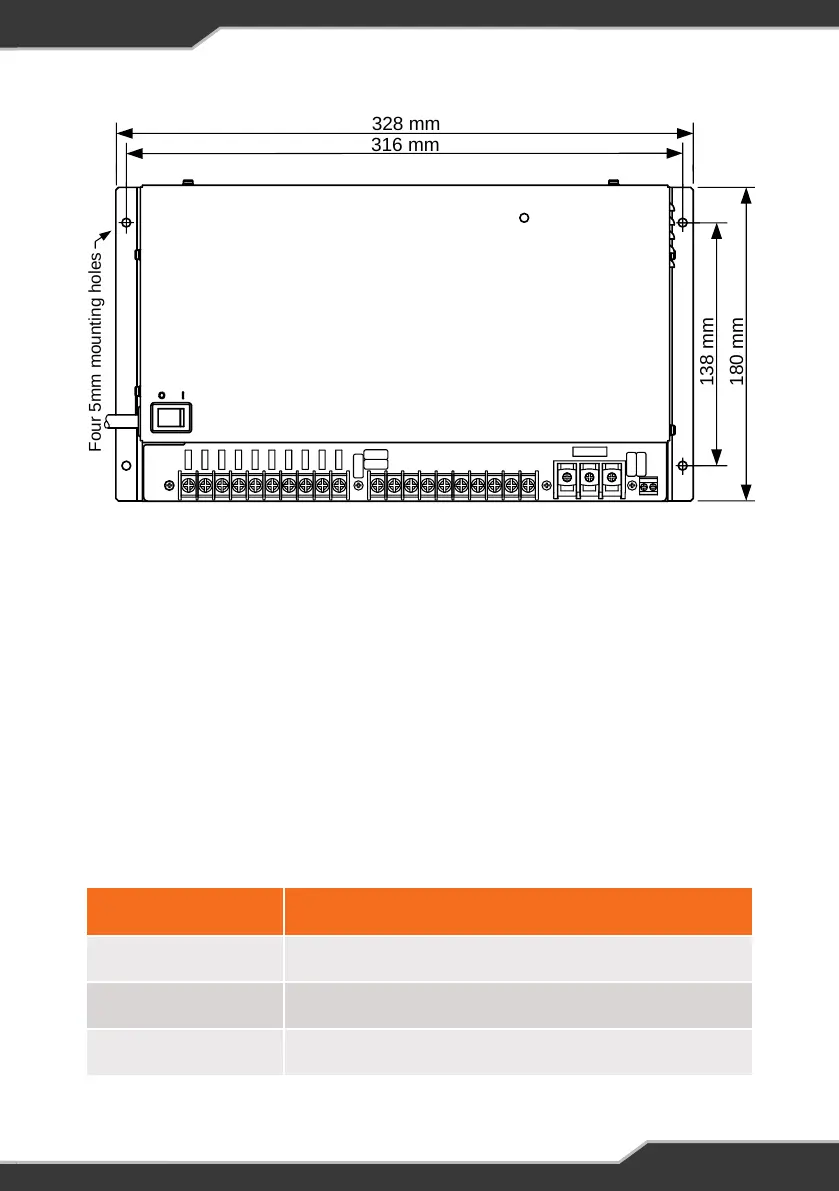
Figure 1: Mounting holes
Load, Battery and External DC Input Connections
All DC connections should be wired according to Figure 3 on page 11.
A block diagram of the basic internal wiring of the Genius-II can be found in
Figure 5 on page 15.
Wire Size
DC cables must be sized to carry the maximum full load current and to not exceed
the system volt drop requirements. The following cable sizes are recommended.
When running wires, if they pass through panels or wall, ensure the wires are
protected from damage by sharp edges. One option is to use cable glands.
Current Minimum Wire Size
0 – 10 A 1.0 mm² or 18 AWG
10 – 20 A 3.0 mm² or 14 AWG
20 – 30 A 5.5 mm² or 10 AWG
Table 2: Wire Size Recommendations
8
Figure 1: Mounting holes
Four 5mm mounting holes
328 mm
316 mm
138 mm
180 mm
LOAD, BATTERY AND EXTERNAL DC INPUT CONNECTIONS
All DC connections should be wired according to Figure 3 on page 13.
A block diagram of the basic internal wiring of the Genius-II can be found in
Figure 5 on page 13.
Wire Size
DC cables must be sized to carry the maximum full load current and to not
exceed the system volt drop requirements. The following cable sizes are
recommended.
When running wires, if they pass through panels or wall, ensure the wires are
protected from damage by sharp edges. One option is to use cable glands.
CURRENT MINIMUM WIRE SIZE
0 — 10A 1.0mm² or 18 AWG
10 — 20 A 3.0mm² or 14 AWG
20 — 30 A 5.5mm² or 10 AWG


 To Next Page