Keyless Controller Shown
A
P–16616
2
4
1
3
STOP
START
RUN
5
7
8
12
11
10
9
13 14
15
Keyless Controller Shown
P–16615
P–16620
16 1817
STOP
START
RUN
P–19199
6
B
P–19200
1
2
3
4 Operation & Maintenance Manual
331/331E/334 Excavator
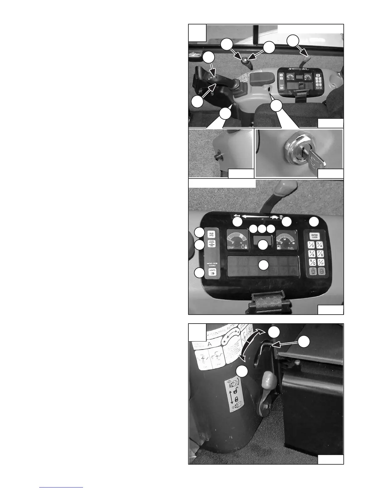
INSTRUMENTS AND CONSOLES (Cont’d)
Right Console [A]
1. Right Control Lever (Joystick) – (See
HYDRAULIC CONTROLS Page 11.)
2. Auxiliary Hydraulics Switch – Controls the fluid
flow to the auxiliary quick couplers (attachment).♦
3. Blade Control Lever – Controls raising and lowering
the blade. (See BLADE CONTROL LEVER, Page
14.)
4. Two–Speed Button – Engages and disengages
High Range travel speed. (See TWO–SPEED
TRAVEL, Page 6.)
5. Speed Control Lever – Controls the RPM of the
engine.
6. Key Switch (Base Panel Only) – (Always perform
the PRE–STARTING PROCEDURE Page 16 before
starting the engine. See STARTING THE ENGINE
Page 19.) (See Item 14 for Keyless Start.)
STOP – Key switch OFF; engine stopped.
RUN (ON) – Position when the engine is running.
START – Start the engine.
NOTE: Always turn key switch and all accessories to
OFF position when the engine is stopped. The
battery will discharge if the key is left ON.
Audible alarm will sound if the key is in the
RUN position with the engine stopped.
7. Auxiliary Power Outlet – Provides 12 Volt
receptacle for accessories.
8. Auxiliary Hydraulic Button – Activates and
deactivates auxiliary hydraulic function.♦
9. HOURS / JOB / RPM – Press to show HOURS, JOB
CLOCK or Engine RPM in LCD (Liquid Crystal
Display, Item 12.)*
10. LIGHTS / HOLD FOR CODES – Press once to turn
lights ON; press again to turn lights OFF. Press and
hold two seconds for display of SERVICE CODES in
LCD (Item 12)
11. TEMPerature Gauge – Shows the engine coolant
temperature.
12. LCD (Liquid Crystal Display) – The LCD is the
HOURMETER during normal operation of the
excavator. When preheat is activated, the LCD will
show remaining preheat time. Can also be used to
display JOB CLOCK or Engine RPM.*
13. FUEL Gauge – Shows the amount of fuel in the tank.
14. Keyless Start (Keyless Controller Only) – (Always
perform the PRE–STARTING PROCEDURE, Page
16 before starting the engine. See STARTING THE
ENGINE Page 19.)
15. Function Icons – (See Function Icons, Page 5.)
16. JOB – On when JOB CLOCK is activated*
17. RPM – On when Engine RPM is activated*
18. ACD – On when Attachment Control Device is
activated*
♦ (See Auxiliary Hydraulics, Page 13.)
* (See SYSTEM SETUP AND ANALYSIS, Page 59.)
STD / ISO SELECTOR VALVE
Move the lever (Item 1) [B] to the front (Item 2) [B] to select
STANDARD Control Pattern. Move to the rear (Item 3) [B]
to select ISO Control Pattern. (See HYDRAULIC
CONTROLS, Page 11.)
 Loading...