CRANKSHAFT (Cont'd)
Installation (Cont'd)
Check the connecting rod bearings using the Plastigage
method. (See Page
78-13.)
Install the
rod
bearings and the correct connecting rod
caps
in
the correct locations and tighten the cap bolts to
specifications.
Install the oil inlet tube and the screen.
Install the crankshaft sprocket and timing chain making
sure that the timing marks are
in
alignment.
Install
the oil thrower timing chain tightener and timing
chain tightener and timing chain cover.
Install the
crankshaft sheave.
Install the oil pan and new gaskets. Tighten the oil pan
fastening bolts to specifications.
(See Page
78-31.)
Turn the engine over again and install the governor drive
belt. Make belt adjustment to specified tension.
Install the
flywheel.
Install
the engine
in
the Bobcat loader.
Fill the crankcase and the cooling system to the correct
level with the specified oil and coolant.
Start the engine
and check for oil and water leaks.
UNIVERSAL JOINT
The tool listed will be needed to do the following
procedure:
MEL 1187 -
Socket
Removal
Remove the engine. (See Page
78-8.)
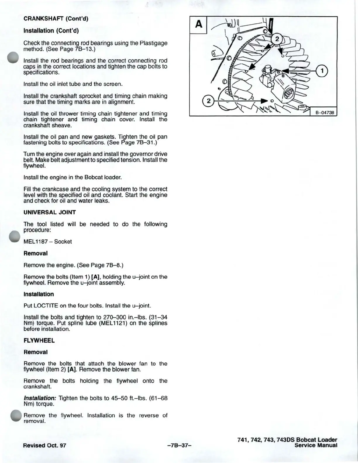
Remove the bolts (Item
1)
[A], holding the u-joint on the
flywheel. Remove the u-joint assembly.
Installation
Put LOCTITE
on
the four bolts. Install the u-joint.
Install the bolts and tighten to
27~300
in.-Ibs.
(31-34
Nm)
torque. Put spline lube (MEL 1121)
on
the splines
before
installation.
FLYWHEEL
Removal
Remove the bolts that attach the blower fan to the
flywheel
(Item 2) [A). Remove the blower fan.
Remove the bolts holding the flywheel onto the
crankshaft.
Installation: Tighten the bolts to
45-50
ft.-Ibs. (61-68
Nm) torque.
Remove the
flywheel. Installation is the reverse of
removal.
Revised Oct.
97
-7B-37-
8-04738
741,742,743, 7430S Bobcat Loader
Service
Manual


 To Next Page
 Loading...