HYDRAULIC CONTROL VALVE (Gresen) (Cont'd)
Removal And
Installation (Cont'd)
Lift and block the loader. (See PREVENTIVE
MAINTENANCE
Section 1.)
Raise the operator cab.
(See PREVENTIVE
MAINTENANCE
Section 1.)
Remove the front panel.
Clean the area around the control valve and use caps and
plugs
in
ports and tubelines.
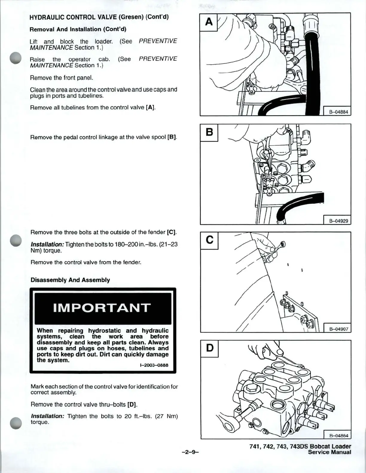
Remove all tubelines from the control valve [A].
Remove the pedal control linkage at the valve spool
[B].
Remove the three bolts at the outside of the fender [C].
Installation: Tighten the bolts to 180-200
in
.
-Ibs
. (21-23
Nm) torque.
Remove the control valve from the fender.
Disassembly And
Assembly
IMPORTANT
When repairing
hydrostatic
and
hydraulic
systems, clean
the
work
area before
disassembly and keep
all
parts
clean.
Always
use
caps and
plugs
on
hoses,
tubelines
and
ports
to
keep
dirt
out.
Dirt
can
quickly
damage
the system.
1-2003-0888
Mark each section of the control valve for identification for
correct assembly.
Remove the control valve thru-bolts
[0].
Installation: Tighten the bolts to 20 ft.
-Ibs
. (27 Nm)
torque.
8
c
D
-2-9-
6--04884
6--04929
6--04907
741,742,743,743DSBobcatLoader
Service Manual