S250 Bobcat Loader
OI-20 Operation & Maintenance Manual
HYDRAULIC CONTROLS (CONT’D)
Auxiliary Hydraulics Button - VARIABLE FLOW
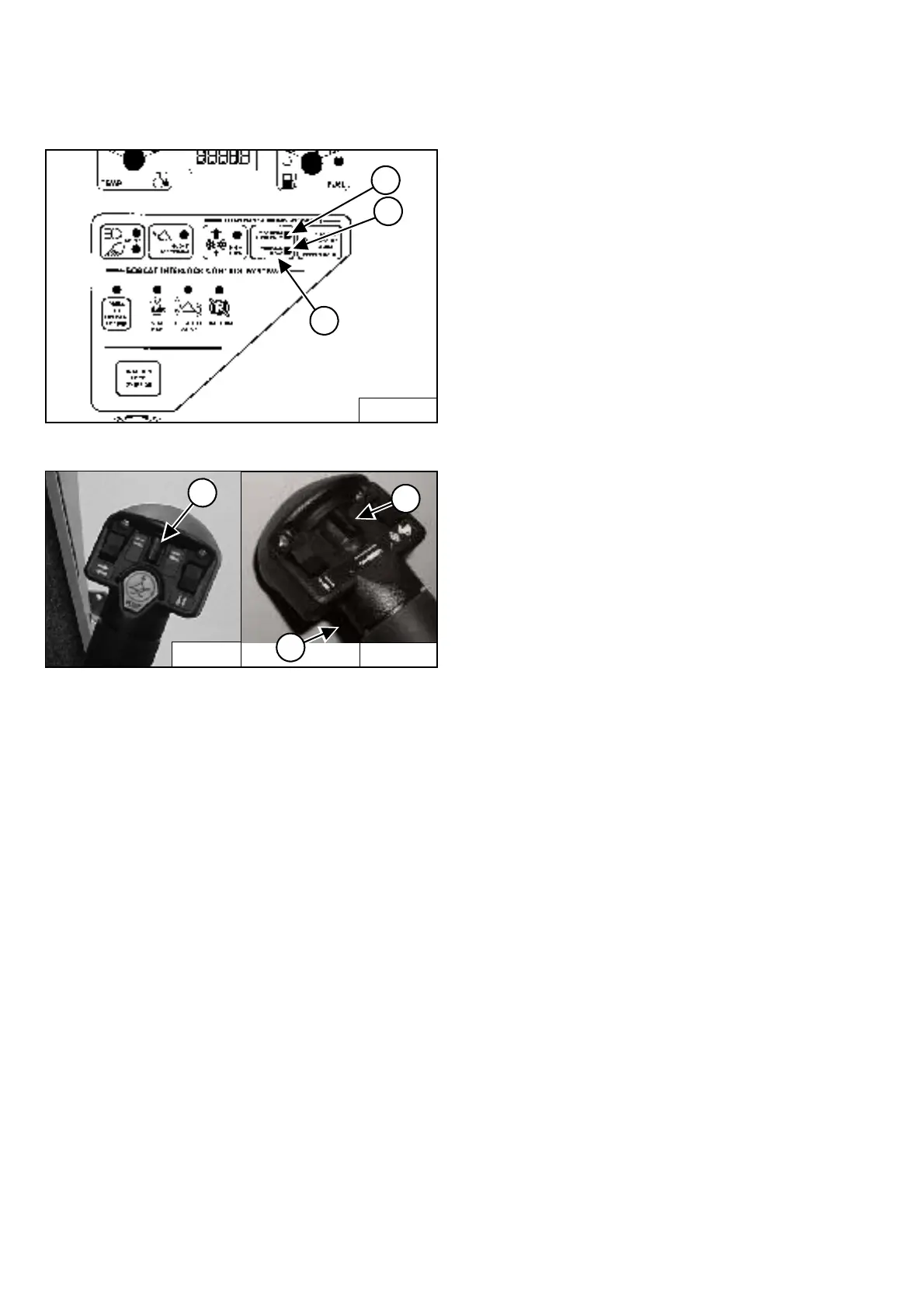
Figure OI-32
Figure OI-33
NOTE: The appearance of Joysticks is different than
handles shown [Figure OI-33] but hydraulic
function is the same.
VARIABLE FLOW allows for slow-to-fast movement of
auxiliary functions. If you move the auxiliary
switch (Item 1) [Figure OI-33] half-way, the auxiliary
functions move at approximately one-half speed.
Press the auxiliary hydraulics button (Item 1)
[Figure OI-32] once.
The light (Item 2) [Figure OI-32] will be ON.
Auxiliary Hydraulics Button - MAXIMUM FLOW ONLY
MAXIMUM FLOW ONLY allows for fast movement only.
If you move the auxiliary switch (Items 1 or 3)
[Figure OI-33], the auxiliary functions move at fast
speed; release the switch to stop auxiliary functions.
Press the auxiliary hydraulics button (Item 1)
[Figure OI-32] a second time.
The light (Item 3) [Figure OI-32] will be ON.
Auxiliary Hydraulics Button - DISENGAGE
To disengage press the auxiliary hydraulics button
(Item 1) [Figure OI-32] a third time.
Both lights (Items 2 & 3) [Figure OI-32] will be OFF.
NOTE: When the operator is seated and raises the
seat bar, the Auxiliary Hydraulic System
(Front and Rear) will deactivate.
FRONT Auxiliary Hydraulics Operation - VARIABLE
FLOW
Press the auxiliary hydraulics button for VARIABLE
FLOW (See Auxiliary Hydraulics Button - VARIABLE
FLOW on Page OI-20).
Push the switch (Item 1) [Figure OI-33] to the right or left
to change the fluid flow direction of the front quick
couplers. (EXAMPLE: Open and close grapple teeth.)
FRONT Auxiliary Hydraulics Operation - MAXIMUM
FLOW
Press the auxiliary hydraulics button for MAXIMUM
FLOW (See Auxiliary Hydraulics Button - MAXIMUM
FLOW ONLY on Page OI-20).
Push the switch (Item 1) [Figure OI-33] to the right or left
to change the fluid flow direction of the front quick
couplers. (EXAMPLE: Open and close grapple teeth.)
FRONT Auxiliary Hydraulics Operation - CONTINUOUS
FLOW
After selecting VARIABLE or MAXIMUM FLOW, press
the front switch (Item 2) [Figure OI-33] to give the front
quick couplers a constant flow of fluid with the female
coupler being pressurized. (EXAMPLE: Operate a
backhoe.)
REVERSE CONTINUOUS FLOW - To set reverse flow
(male coupler pressurized), hold the auxiliary
switch (Item 1) [Figure OI-33] to the left, press
VARIABLE or MAXIMUM FLOW and then press the front
switch (Item 2) [Figure OI-33]. Reverse flow can be used
only with augers, power rakes, sweepers, tillers, and
vibratory rollers.
To release from continuous operation, press the front
switch (Item 2) [Figure OI-33] a second time.
B-15551
2
1
3
P-31833
2
1
3
P-16537
 Loading...