177 S650 Operation & Maintenance Manual
DRIVE BELT (CONT’D)
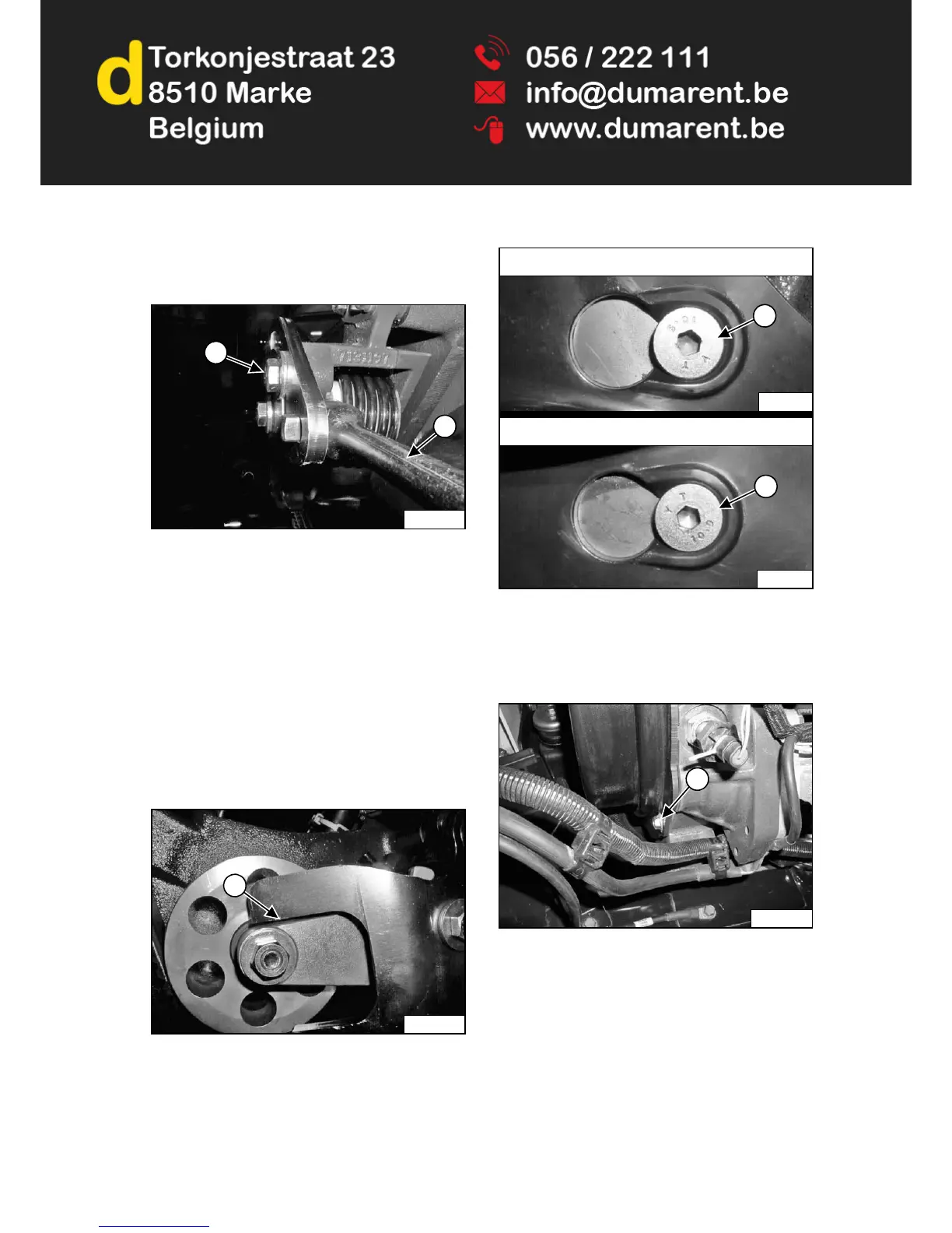
Belt Replacement (Cont’d)
Figure 272
Loosen the spring loaded idler adjustment bolt (Item 1).
Insert a 1/2 in. breaker bar (Item 2) [Figure 272] into the
slot provided in the stop arm as shown and push breaker
bar down to release tension on drive belt.
Tighten the adjustment bolt (Item 1) [Figure 272] to hold
the spring loaded idler off the drive belt.
Remove the drive belt from the hydrostatic pump pulley
and flywheel pulley. Inspect the pulleys for wear.
Install new drive belt.
Loosen the spring loaded idler adjustment bolt (Item 1)
[Figure 272] and allow the idler to contact the drive belt.
Figure 273
Move the breaker bar to adjust the stop arm until a gap of
3,2 mm (0.125 in) (Item 1) [Figure 273] is achieved.
Tighten the spring loaded idler adjustment bolt (Item 1)
[Figure 272] to 105 - 115 N•m (78 - 85 ft-lb) torque.
Figure 274
Position the drive belt shield over the drive belt shield
mounting bolts and slide the drive belt shield toward the
front of the loader to fully seat the shield onto the top and
bottom mounting bolts (Items 1 and 2) [Figure 274].
Figure 275
Install the drive belt shield bolt (Item 1) [Figure 275].
Install the battery. (See Removing And Installing Battery
on Page 163.)
Close the rear door.
P-90470
1
2
P-90471
1
P-90468A
1
Top Mounting Bolt
P-90469A
2
Bottom Mounting Bolt
P-85518
1