– 4 –
A thermostatically controlled anti-scald valve meeting requirements of CSA B125 or ASSE 1016 or
1017 should be used to temper the domestic hot water supply to fixtures to 49
O
C (120
O
F). See
Figure1 for proper installation of antiscald valve.
The temperature and pressure (T&P) relief valve has been factory installed.
To prevent water damage when relief occurs, install a discharge line from the relief valve outlet to a
place
for water disposal. Do not install a reducing coupling or other restriction in the dis charge line.
Arrange the line to allow com plete drainage of both the relief valve and the discharge line. If the T&P
relief valve discharges periodically, service to the water system is required.
Do not place a shut-off valve between the relief valve and the water heater.
Check hand holes for tightness.
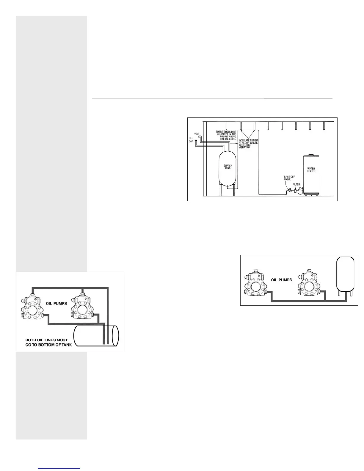
The oil tank location and installation, tank size, piping supply and burners, including all fuel handling com-
ponents must comply with the applicable codes for oil-burning equipment (CAN/CSA-B139 or NFPA 31,
local codes and regulations).
The oil supply tank must be installed
with fill and vent lines of adequate
capacity. See Figure 2 for installation
diagram.
The water heater requires fuel (#1 or
#2 heating oil), electricity and
should be closed to the chimney
and water supply. Do not use gaso-
line, crankcase drainings, or any oil
containing gasoline. Never burn
garbage or paper in the unit, and
never leave paper or rags around it.
1. The op er at ing thermostat and high
limit are packed with the burner.
Mount the burner with bolts pro vid ed. Burners are shipped with all settings at the approximate start
point.
Check in side the com bus tion cham ber to verify that the burn er tube is not ob struct ed or pro-
truding into the cham ber. Swing back the hinged trans form er and rotate the blower wheel by hand a
few turns to loosen the pump seal.
2. Bock rec om mends a two-pipe (suction and return) system for these heat ers. Use 1/2" O.D. soft cop -
per tub ing (5/8” O.D. soft copper on Sun Tec H pumps) and
install a by pass plug on two-pipe system. (See instructions
packed with pump.) Note: Do not install a bypass plug if us -
ing a gravity (one-pipe) system (See Fig ure 3.) For mul ti ple
heater in stal la tions, run a separate suction
and re turn line for each heater (See Figure 4.)
If t
he com bined lift and hor i zon tal run ex ceeds
100’, install a boost er pump as close to the
supply tank as possible.
Booster
pumps may be obtained from Sun
Tec Hy drau lics, Rockford, Ill.
3. Return lines must be the same diameter as suction lines and extend close to the bot-
tom of storage tank but stop slightly above suc tion lines. Use a minimum of fittings and
make bends in tubing with as large a radius as possible. Always use flared fittings, not
com pres sion fittings. If pipe is used instead of tubing, do not connect the burner to the
pipe
– use copper tubing and form a coil be fore at tach ing tubing to burner.
4. When installing an oil water heater with an existing oil tank and lines, check existing line sizes and
compare to instructions shipped with the pump to see if they are ad e quate. Do not use ex ist ing lines
if they are smaller than 1/2" O.D. tube on Models 361E and 541E. Pro ceed as fol lows:
A.
If existing oil heater has a one-pipe sys tem, tee into the sys tem to furnish oil to the heater.
B. If the existing oil heater has a two-pipe system, check wheth er the return line ex tends to the bot-
tom of the tank. It may be preferable to change the existing oil heat er to a one-pipe sys tem and
change the re turn line to the suction line for the heat er.
C. If (B) is not applic
able, tee into the ex ist ing suction line and the existing return line to supply oil to
the heater. Both suc tion and return lines must extend to the bottom of the tank, but if the tubing is too
small and a two-stage pump is on the ex ist ing oil appliance, the water heater pump may be starved
for oil.
D. If return lines do not extend to the bottom of the tank, use check valves on each suction line as close
Install a water soft -
en er if the heater is
being used in a hard
water area (wa ter
hardness of more
than sev en grains).
GRAVITY SYS TEM
FIGURE 3
FIGURE 4
T&P RELIEF VALVE
ATTACH BURNER
& OIL LINES
FIGURE 2
OIL SUPPLY
 Loading...